Dodge Caliber. Manual - part 1193


  Index      Dodge     Dodge Caliber - service repair manual 2007 year


Search            


Content   ..  1191  1192  1193  1194   ..


Dodge Caliber. Manual - part 1193


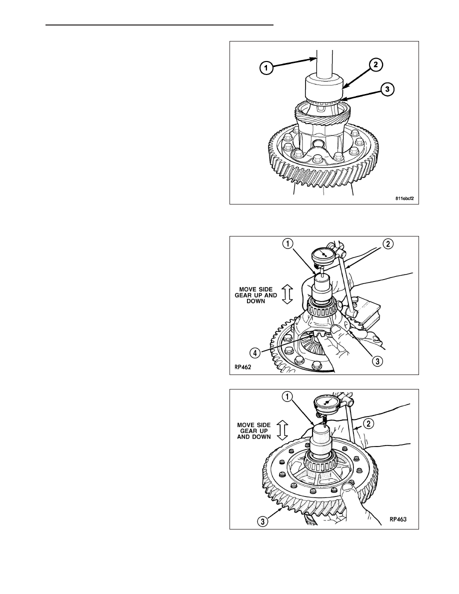
8. Using an arbor press, Handle C-4171 (1), and

Installer L-4410 (2), install differential side bearings
(3) to case side.

Measure and Adjust Side Gear End-Play

1. Rotate the assembly (3) two full revolutions both

clockwise and counterclockwise. Set up dial indica-
tor (2) and record end play.

2. Rotate side gear 90 degrees and take another

measurement (2). Again, rotate side gear 90
degrees and record a final measurement.

3. Using the smallest end play recorded, shim that

side gear to within 0.001 to 0.013 inch. The other
side gear should be checked using the same pro-
cedure.

CAUTION: Side gear end play must be within 0.001
to 0.013 inch.

PM

T355 MANUAL TRANSAXLE

21 - 71

ADJUSTMENTS

DIFFERENTIAL BEARING PRELOAD ADJUSTMENT / SHIM SELECTION

Measure and adjust differential side bearing preload
during any transaxle service, especially when the fol-
lowing components are replaced:

Transaxle gear case

Clutch bellhousing case

Differential case

Differential bearings

NOTE: True bearing turning torque readings can
be obtained only with the geartrain removed from
the case.

1. Remove bearing cup and existing shim from clutch

bellhousing case.

2. Press in new bearing cup into bellhousing case (or

use a cup that has been ground down on the outer
edge for ease of measurement).

3. Press in new bearing cup into gear case side.

4. Oil differential bearings with transmission fluid. Install differential assembly in transaxle gear case. Install clutch

bellhousing over gear case. Install and torque case bolts to 29 N·m (19 ft. lbs.).

5. Position transaxle with bellhousing facing down on workbench with C-clamps. Position dial indicator (2).

NOTE: Indicator is set up as shown for illustrative purposes only. Indicator must be parallel to T-Handle to
obtain the most accurate reading.

6. Apply a medium load to differential with Torque Tool C-4995 (3) and a T-handle (1), in the downward direction.

Roll differential assembly back and forth a number of times. This will settle the bearings. Zero the dial indicator
(2). To obtain end play readings, apply a medium load in an upward direction while rolling differential assembly
back and forth. Record end play.

7. The shim required for proper bearing preload is the

total of end play, plus (constant) preload of 0.18
mm (0.007 in.). 
Never combine shims to obtain the
required preload.

8. Remove case bolts. Remove clutch bellhousing dif-

ferential bearing cup. Install shim(s) selected in
Step 7. Then press the bearing cup into clutch bell-
housing.

9. Install clutch bellhousing. Install and torque case

bolts to 29 N·m (19 ft. lbs.).

10. Using Torque Tool C-4995 (2) and an inch-pound

torque wrenched (1) check turning torque of the
differential assembly. The turning torque should
be 6 to 12 in. lbs. If the turning torque is too
high, install a 0.05 mm (0.002 inch) thinner
shim. If the turning torque is too low, install a
0.05mm (0.002 inch) thicker shim.

11. Recheck turning torque. Repeat Step 10 until the proper turning torque is obtained.

21 - 72

T355 MANUAL TRANSAXLE

PM

CUPS-DIFFERENTIAL BEARING

REMOVAL

1. Remove differential assembly from gear case (2)

using the procedure outlined in this group.

2. Install Remover L-4518 (1) into the differential

bearing cup.

3. Install the tool cup (2) over the tool.

4. Tighten the tool until the race is removed from the

case.

INSTALLATION

1. Position the bearing cup into the case.

2. Install the bearing cup onto Installer L-4520.

3. Using Installer L-4520 and Universal Handle C-4171, install differential bearing cup into the transaxle case.

PM

T355 MANUAL TRANSAXLE

21 - 73

FLUID

STANDARD PROCEDURE - FLUID DRAIN AND FILL

NOTE: All T355 Manual Transaxles require the use
of ATF+4 (Automatic Transmission Fluid).

The transaxle fill plug (1) is located on the left side of
the transaxle differential area. The fluid level should
be within 3/16 inch from the bottom of the transaxle fill
hole (vehicle must be level when checking).

The transaxle drain plug (1) is located on the lower
right side of the transaxle differential housing. Tighten
drain plug to 14 N·m (120 in. lbs.).

21 - 74

T355 MANUAL TRANSAXLE

PM


Content   ..  1191  1192  1193  1194   ..