Dodge Caliber. Manual - part 1160


  Index      Dodge     Dodge Caliber - service repair manual 2007 year


Search            


Content   ..  1158  1159  1160  1161   ..


Dodge Caliber. Manual - part 1160


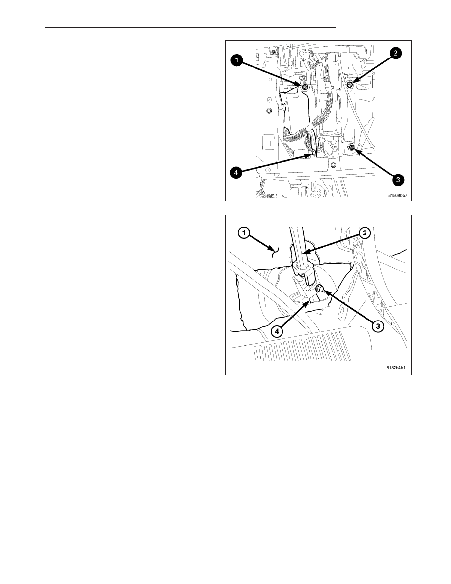
4. Starting with the left upper nut and proceeding in a

clockwise tightening sequence ending at the bolt
(left lower) (2), Tighten all four mounting fasteners
to 28 N·m (21 ft. lbs.).

5. Verify the front wheels of vehicle are in the

STRAIGHT-AHEAD position.

6. Collapse the intermediate shaft (2). Center it over

the steering gear pinion shaft (4), lining up the
ends, then slide the intermediate shaft onto the
steering gear pinion shaft. Do not install the
pinch bolt (3) at this time. The pinch bolt can
be more easily installed in a later step.

7. If the vehicle is equipped with an automatic transaxle, connect the ignition shift interlock cable to the steering

column.

PM

COLUMN

19 - 27

8. Connect the wiring harness connectors (2) to the

Steering Column Control Module (SCCM) (1).

9. Connect any other the wiring harness connectors.

10. Push the tilt lever (5) downward.

11. Install the lower shroud (2) over the tilt lever and

onto the column.

12. Position the column tilt (5) at the full-upward posi-

tion.

13. Push the tilt lever (5) upward, locking it in place.

14. Install the screw (3) attaching the lower shroud (2)

to the steering column (6).

15. Position the column tilt at the full-downward posi-

tion and lock it in place.

16. Install the upper shroud over the lower shroud,

clipping the shrouds to one another.

17. Install the two screws (4) attaching the upper

shroud (1) to the lower shroud (2).

18. Position the column tilt at the full-upward position.

19. Install the steering column reinforcement panel (1)

and four screws (2).

19 - 28

COLUMN

PM

20. Install the steering column opening cover (Refer

to 23 - BODY/INSTRUMENT PANEL/STEERING
COLUMN OPENING COVER - INSTALLATION).

21. Install the IP side trim (Refer to 23 - BODY/IN-

STRUMENT PANEL/INSTRUMENT PANEL END
CAP - INSTALLATION).

CAUTION: When installing the steering wheel, the
clockspring must be centered in its travel to avoid
overextending the clockspring inner parts, causing
the clockspring to become inoperative. If removed
and handled properly using the correct proce-
dures, it should be in the “centered” position. If
there is any question as to whether the clock-
spring is in the “centered” position of travel, per-
form the clockspring centering procedure before
proceeding.

(Refer

to

8

-

ELECTRICAL/RE-

STRAINTS/CLOCKSPRING - STANDARD PROCE-
DURE)

22. Install the steering wheel (2) and the retaining bolt

(4). Tighten the steering wheel retaining bolt to 43
N·m (32 ft. lbs.) (Refer to 19 - STEERING/COL-
UMN/STEERING WHEEL - INSTALLATION).

23. Install the speed control switch mounting screw

(3).

PM

COLUMN

19 - 29

24. Connect

the

wiring

connector

(2)

at

the

clockspring.

25. Install the driver airbag (3). (Refer to 8 - ELEC-

TRICAL/RESTRAINTS/DRIVER

AIRBAG

-

INSTALLATION)

26. From center, rotate the steering wheel to the right

approximately 90° or until the shaft coupling pinch
bolt (3) can be easily installed.

27. Install the pinch bolt (3). Tighten the pinch bolt to

28 N·m (21 ft. lbs.).

28. Reposition the floor carpet (1) in place.

29. Straighten the steering wheel to STRAIGHT-

AHEAD position.

19 - 30

COLUMN

PM


Content   ..  1158  1159  1160  1161   ..