Dodge Caliber. Manual - part 1158


  Index      Dodge     Dodge Caliber - service repair manual 2007 year


Search            


Content   ..  1156  1157  1158  1159   ..


Dodge Caliber. Manual - part 1158


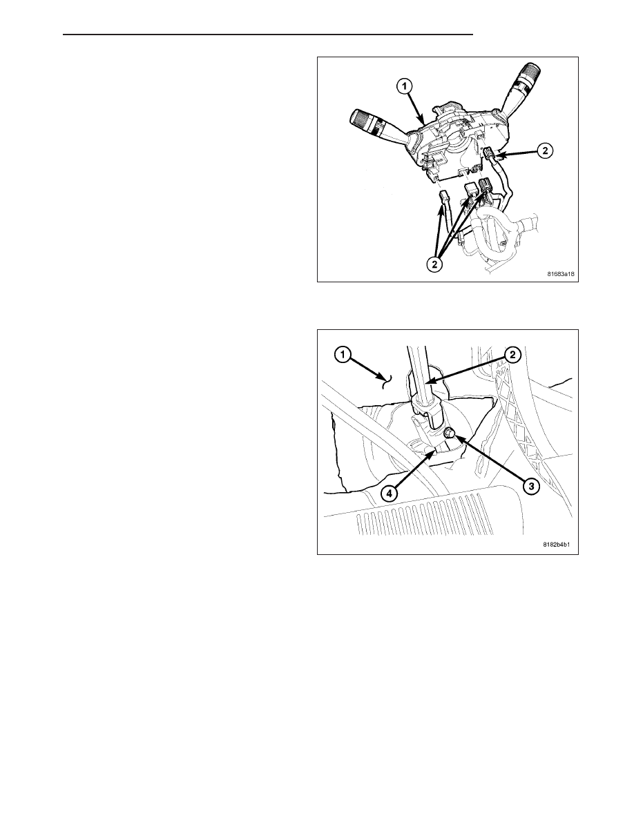
21. Disconnect the wiring harness connectors (2) at

the Steering Column Control Module (SCCM) (1).

22. Disconnect all other wiring harness connectors at

column components.

23. If the vehicle is equipped with an automatic transaxle, disconnect the ignition shift interlock cable at the steering

column.

24. Separate the intermediate shaft (2) at the base of

the column from the steering gear pinion shaft (2).

PM

COLUMN

19 - 19

NOTE: If the same steering column is to be rein-
stalled, clamp the tilt lever to lock the column in
place so that it can be easily reinstalled in the
same orientation.

25. Remove the three mounting nuts (1) attaching the

steering column to the instrument panel (3).

26. Remove the one mounting bolt (left lower) (2)

attaching the steering column to the instrument
panel (3).

27. Remove the steering column from the vehicle.

28. To remove remaining components from the col-

umn, (Refer to 19 - STEERING/COLUMN -
DISASSEMBLY).

DISASSEMBLY

STEERING COLUMN CONTROL MODULE

1. Remove the screws (1) attaching the Steering Col-

umn Control Module (SCCM) (with switch stalks)
(3) to the steering column (2).

2. Slide the SCCM (with switch stalks) (3) off the

steering column (2).

19 - 20

COLUMN

PM

SKREEM/WCM (IF EQUIPPED)

NOTE: SCCM previously removed.

1. Remove the screw (1) fastening the SKREEM/

WCM (2) to the lock cylinder housing (3).

2. Unhook the SKREEM/WCM (2) retainer fingers

from the lock cylinder housing (3) and remove it
from the housing.

KEY CYLINDER

NOTE:

SCCM

and

SKREEM/WCM

previously

removed.

1. Insert the key (2) and turn the key cylinder (3) to

the RUN position.

2. Insert an appropriate tool into the slot (1) formed

into the lock cylinder housing depressing the key
cylinder retaining tab.

3. Pull the key cylinder and key straight out of the

lock cylinder housing as one unit.

PM

COLUMN

19 - 21

LOCK CYLINDER HOUSING

NOTE: SCCM previously removed.

1. Using Tamper-Proof Torx

T

Plus (five point) 30 bit,

remove the two screws (1) fastening the lock cylin-
der housing (2) to the column.

2. Remove the lock cylinder housing from the steering

column.

IGNITION SWITCH

NOTE: Lock cylinder housing previously removed.

1. Lower the column tilt lever to the full-downward

position.

2. Remove the ignition switch (2) mounting screw (1).

19 - 22

COLUMN

PM


Content   ..  1156  1157  1158  1159   ..