Dodge Caliber. Manual - part 33


  Index      Dodge     Dodge Caliber - service repair manual 2007 year


Search            


Content   ..  31  32  33  34   ..


Dodge Caliber. Manual - part 33


INSTALLATION

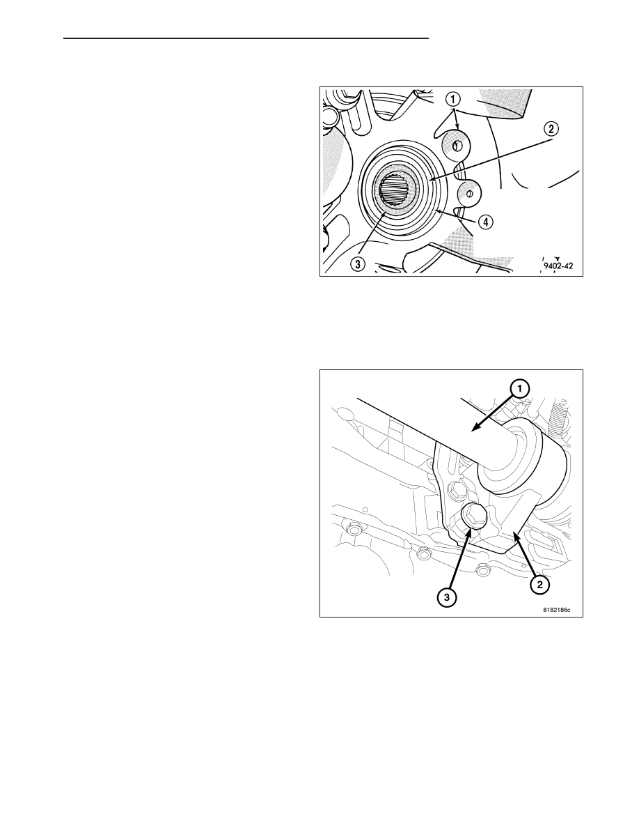
1. Clean all debris and moisture out of steering

knuckle (4).

CAUTION: Boot sealing is vital to retain special
lubricants and to prevent foreign contaminants
from entering the CV joint. Mishandling, such as
allowing the assemblies to dangle unsupported, or
pulling or pushing the ends can cut boots or dam-
age CV joints. During removal and installation pro-
cedures, always support both ends of the halfshaft
to prevent damage.

2. Thoroughly clean spline and oil seal sealing sur-

face, on tripod joint. Lightly lubricate oil seal seal-
ing

surface

on

tripod

joint

with

fresh

clean

transmission lubricant.

3. Holding halfshaft assembly by tripod joint and inter-

connecting shaft, install tripod joint into transaxle side gear as far as possible by hand.

4. Carefully align tripod joint with transaxle side gears. Then grasp halfshaft interconnecting shaft and push tripod

joint into transaxle side gear until fully seated. Test that snap ring is fully engaged with side gear by attempt-
ing to remove tripod joint from transaxle by hand. If snap ring is fully engaged with side gear, tripod joint
will not be removable by hand.

5. If the vehicle is two wheel drive install the halfshaft

bracket (2) to engine lower mounting bolt (3) and
torque to 75 N·m (55 ft. lbs.).

PM

HALF SHAFT-FRONT

3 - 7

6. If the vehicle is two wheel drive install the halfshaft

bracket upper mounting bolts (2) and torque to 75
N·m (55 ft. lbs.).

7. Ensure that front of outer CV joint (2) which fits into

steering knuckle, is free of debris and moisture
before assembling into steering knuckle.

8. Apply a light coating of MOPAR

T

multi-purpose

wheel bearing grease around the circumference of
the flat surface (1). Do not apply too much
grease, which could spill on to the non mating
and adversely affect the function of the half-
shaft.

9. Wipe the rear of the hub and bearing in the

knuckle clean where they contact the C/V joint.

10. Install halfshaft back into front hub.

3 - 8

HALF SHAFT-FRONT

PM

11. Install steering knuckle onto the ball joint stud (3).

NOTE: At this point, the outer joint will not seat
completely into the front hub. The outer joint will
be pulled into hub and seated when the hub nut is
installed and torqued.

12. Install a NEW steering knuckle to ball joint stud

bolt (2) and nut (1). Tighten the nut and bolt to 95
N·m (70 ft. lbs.).

13. Clean all foreign matter from threads of halfshaft

outer stub axle. Install washer (2) and hub nut (3)
onto the threads of the stub axle and tighten nut
(3) to 244 N·m (180 ft. lbs.).

14. Install spring washer (4), nut lock (5), and cotter

pin (1).

15. Install front wheel and tire assembly (1). Install

front wheel lug nuts (2) and tighten to 128 N·m
(95 ft. lbs.).

16. Check for correct fluid level in transaxle assembly.

17. Lower vehicle.

18. Connect battery negative cable.

Halfshaft Retaining Hardware

1 - COTTER PIN
2 - WASHER
3 - HUB NUT
4 - SPRING WASHER
5 - NUT LOCK

PM

HALF SHAFT-FRONT

3 - 9

SPECIFICATIONS

TORQUE

DESCRIPTION

N·m

Ft. Lbs.

In. Lbs.

Bolt, Intermediate Shaft

Bracket-block

75

55

-

Nut, Driveshaft-to-Hub/

Bearing

244

180

-

Nut, Knuckle-to-Ball Joint

Bolt

95

70

-

Nut, Wheel to Hub

128

95

-

SPECIAL TOOLS

HALFSHAFT

Puller 1026

Crimping Tool C-4975A

3 - 10

HALF SHAFT-FRONT

PM


Content   ..  31  32  33  34   ..