Dodge Caliber. Manual - part 32


  Index      Dodge     Dodge Caliber - service repair manual 2007 year


Search            


Content   ..  30  31  32  33   ..


Dodge Caliber. Manual - part 32


2. Damaged outer CV or inner tripod joint seal boot or seal boot clamps, which is evident by the presence of

grease slung outward from the joint. This will result in the loss and/or contamination of the joint grease, resulting
in inadequate lubrication of the joint.

3. Noise may also be caused by another component of the vehicle coming in contact with the halfshafts.

CLUNKING NOISE DURING ACCELERATION

This noise may be a result of one of the following conditions:

1. A torn seal boot on the inner or outer joint of the halfshaft assembly, which is evident by the presence of grease

slung outward from the joint. This will result in the loss and/or contamination of the joint grease, resulting in
inadequate lubrication of the joint.

2. A loose or missing clamp on the inner or outer joint of the halfshaft assembly. This may be accompanied by the

visible loss of grease.

3. A damaged or worn halfshaft CV joint. Isolate the noise to one side of the vehicle. Replace only the affected

side. Replacing both halfshafts is not necessary.

SHUDDER OR VIBRATION DURING ACCELERATION

1. A worn or damaged halfshaft inner tripod joint. Isolate the condition to one side of the vehicle. Replace only the

affected side. Replacing both halfshafts is not necessary.

2. A sticking tripod joint spider assembly (inner tripod joint only). Isolate the condition to one side of the vehicle.

Replace only the affected side. Replacing both halfshafts is not necessary.

3. Improper wheel balance.

VIBRATION AT HIGHWAY SPEEDS

1. Foreign material (mud, etc.) packed on the backside of the wheel(s).

2. Out of balance front tires or wheels.

3. Improper tire and/or wheel runout.

REMOVAL

CAUTION: Boot sealing is vital to retain special
lubricants and to prevent foreign contaminants
from entering the CV joint. Mishandling, such as
allowing the assemblies to dangle unsupported, or
pulling or pushing the ends can cut boots or dam-
age CV joints. During removal and installation pro-
cedures, always support both ends of the halfshaft
to prevent damage.

CAUTION: The halfshaft, when installed, acts as a
bolt and secures the front hub/bearing assembly. If
vehicle is to be supported or moved on its wheels
with a halfshaft removed, install a PROPER–SIZED
BOLT AND NUT through front hub. Tighten bolt
and nut to 244 N·m (180 ft. lbs.). This will ensure that the hub bearing cannot loosen.

1. Disconnect battery negative cable.

2. Place transaxle in gated park.

3. Raise vehicle on hoist.

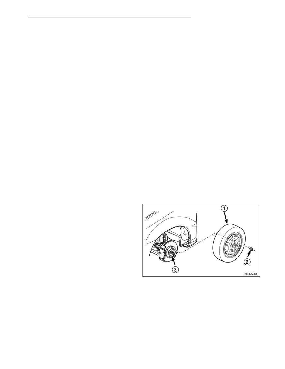
4. Remove wheel and tire assembly (1).

PM

HALF SHAFT-FRONT

3 - 3

5. Remove the cotter pin (1), nut lock (5), spring

washer (4), and hub nut (3) from the end of the
outer C/V joint stub axle.

6. If equipped with ABS, disconnect the front wheel

speed sensor and secure harness out of the way.

7. Remove nut and bolt (1,2) retaining ball joint stud

(3) into steering knuckle.

NOTE: Use caution when separating ball joint stud
from steering knuckle, so ball joint seal does not
get damaged.

8. Separate ball joint stud (4) from steering knuckle

(1) by prying down on lower control arm (3).

Halfshaft Retaining Hardware

1 - COTTER PIN
2 - WASHER
3 - HUB NUT
4 - SPRING WASHER
5 - NUT LOCK

3 - 4

HALF SHAFT-FRONT

PM

NOTE: Care must be taken not to separate the
inner CV joint during this operation. Do not allow
halfshaft to hang by inner CV joint, halfshaft must
be supported.

9. Remove halfshaft (2) from steering knuckle by pull-

ing outward on knuckle while pressing in on half-
shaft. Support outer end of halfshaft assembly. If
difficulty in separating halfshaft from hub is encoun-
tered, do not strike shaft with hammer, instead
use Puller 1026 (1) to separate.

10. If the vehicle is two wheel drive remove the half-

shaft bracket (2) to engine lower mounting bolt
(3).

PM

HALF SHAFT-FRONT

3 - 5

11. If the vehicle is two wheel drive remove the half-

shaft bracket to engine upper mounting bolts (2).

12. Support outer end of the halfshaft assembly.

NOTE: Removal of the inner tripod joints is made
easier if you apply outward pressure on the joint
as you strike the punch with a hammer. Do not
pull on interconnecting shaft to remove, as the
inner joint will become separated.

13. Remove the inner tripod joints (4) from the side

gears of the transaxle using a punch (2) to dis-
lodge the inner tripod joint retaining ring from the
transaxle side gear. If removing the right side
inner tripod joint, position the punch to the inner
tripod joint extraction groove (5) (if equipped).
Strike the punch sharply with a hammer to dis-
lodge the right inner joint from the side gear. If
removing the left side inner tripod joint, position
the punch to the inner tripod joint extraction
groove. Strike the punch sharply with a hammer
to dislodge the left inner tripod joint from the side gear.

14. Hold inner tripod joint (1) and interconnecting

shaft (6) of halfshaft assembly. Remove inner tri-
pod joint from transaxle by pulling it straight out of
transaxle side gear and transaxle oil seal (4).
When removing tripod joint, do not let spline
or snap ring drag across sealing lip of the
transaxle to tripod joint oil seal. When tripod
joint is removed from transaxle, some fluid
will leak out.

CAUTION: The halfshaft, when installed, acts as a
bolt and secures the front hub/bearing assembly. If
vehicle is to be supported or moved on its wheels
with a halfshaft removed, install a PROPER–SIZED
BOLT AND NUT through front hub. Tighten bolt
and nut to 244 N·m (180 ft. lbs.). This will ensure
that the hub bearing cannot loosen.

3 - 6

HALF SHAFT-FRONT

PM


Content   ..  30  31  32  33   ..