Dodge Caliber. Manual - part 31


  Index      Dodge     Dodge Caliber - service repair manual 2007 year


Search            


Content   ..  29  30  31  32   ..


Dodge Caliber. Manual - part 31


TOE

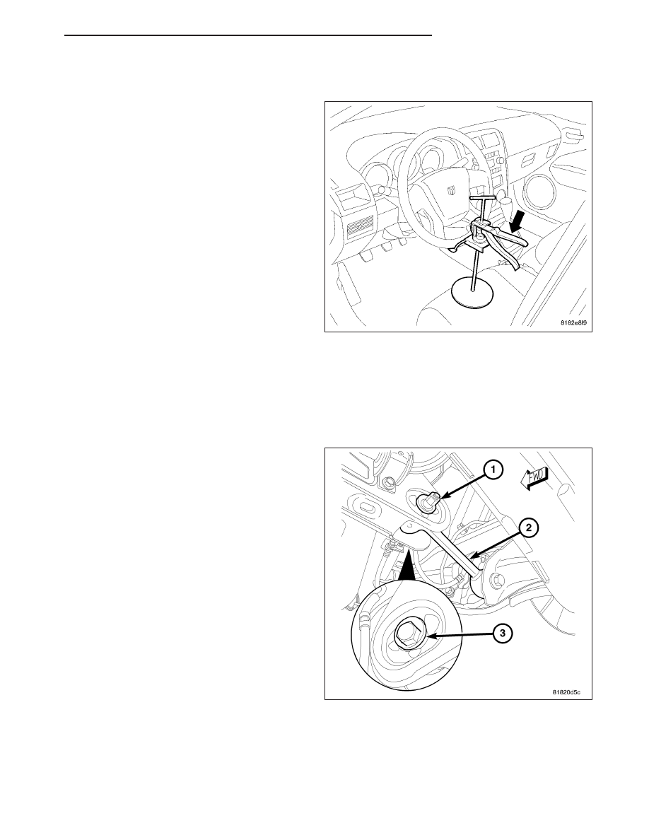
1. Center the steering wheel and lock it in place using

a steering wheel clamp.

NOTE: When setting toe, make sure to set rear toe to the preferred specifications before setting front toe to
the preferred specifications

REAR TOE

NOTE: Perform the following at each rear wheel as necessary.

1. While holding the cam bolt head (3) stationary,

loosen the toe link mounting cam bolt nut (1).

2. Rotate the cam bolt head (3) left or right until the

rear wheel toe for that rear wheel is set to the pre-
ferred specification. (Refer to 2 - SUSPENSION/
WHEEL ALIGNMENT - SPECIFICATIONS)

3. While holding the cam bolt head (3) stationary,

tighten the toe link mounting cam bolt nut (1) to 25
N·m (18 ft. lbs.).

FRONT TOE

CAUTION: Do not twist the inner tie rod-to-steering gear rubber boots while turning the inner tie rods during
the front toe adjustment.

NOTE: Perform the following at each front wheel as necessary.

PM

WHEEL ALIGNMENT

2 - 89

1. Loosen the tie rod adjusting jam nut (1). Grasp the

inner tie rod (3) and rotate it one way or the other
until the front wheel toe is set to the preferred
specification. (Refer to 2 - SUSPENSION/WHEEL
ALIGNMENT - SPECIFICATIONS)

2. Tighten the tie rod adjusting jam nut to of 75 N·m

(55 ft. lbs.).

3. Make sure the inner tie rod-to-steering gear rubber

boot is not twisted.

2. Remove the steering wheel clamp.

3. Remove the alignment equipment.

4. Road test the vehicle to verify the steering wheel is straight and the vehicle does not pull or wander.

SPECIFICATIONS

WHEEL ALIGNMENT

NOTE: All specifications are given in degrees.

NOTE: All wheel alignments are to be set with the vehicle at curb height. (Refer to 2 - SUSPENSION/WHEEL
ALIGNMENT - STANDARD PROCEDURE)

FRONT WHEEL ALIGNMENT

PREFERRED SETTING

ACCEPTABLE RANGE

CAMBER

-0.43°

-0.83° to -0.03°

Cross Camber (Maximum Side-To-
Side Difference)

0.00°

0.50

CASTER*

+2.50°

+1.50° to +3.50°

Cross Caster (Maximum Side-To-Side
Difference)

0.00°

1.00°

TOE - INDIVIDUAL

+0.05°

-0.05° to +0.15°

TOE - TOTAL**

+0.10°

-0.10° to +0.30°

REAR WHEEL ALIGNMENT

PREFERRED SETTING

ACCEPTABLE RANGE

CAMBER*

-0.50°

-0.90° to -0.10°

TOE - INDIVIDUAL

+0.10°

0.00° to +0.20°

TOE - TOTAL**

+0.20°

0.00° to +0.40°

THRUST ANGLE

0.00°

-0.10° to +0.10°

Notes:

* For reference only. These are nonadjustable angles.

** TOTAL TOE is the sum of both the left and right wheel toe settings. TOTAL TOE must be equally split between
each wheel on the same axle to ensure the steering wheel is centered after setting toe.

Positive toe (+) is toe-in and negative toe (

2

) is Toe-out.

2 - 90

WHEEL ALIGNMENT

PM

DIFFERENTIAL & DRIVELINE

TABLE OF CONTENTS

page

page

HALF SHAFT-FRONT

. . . . . . . . . . . . . . . . . . . . . . 1

HALF SHAFT-LEFT REAR

. . . . . . . . . . . . . . . . . 21

HALF SHAFT-RIGHT REAR

. . . . . . . . . . . . . . . . 32

SHAFT-PROPELLER

. . . . . . . . . . . . . . . . . . . . . . 43

MODULE-REAR DRIVELINE

. . . . . . . . . . . . . . . . 50

CLUTCH-ELECTRONICALLY CONTROLLED-

ELECTRICAL DIAGNOSTICS . . . . . . . . . . . . . . . 86

CLUTCH-ELECTRONICALLY CONTROLLED-

SERVICE INFORMATION . . . . . . . . . . . . . . . . . 143

HALF SHAFT-FRONT

TABLE OF CONTENTS

page

page

HALF SHAFT-FRONT

DESCRIPTION . . . . . . . . . . . . . . . . . . . . . . . . . . . . . . . . . 2
OPERATION . . . . . . . . . . . . . . . . . . . . . . . . . . . . . . . . . . . 2
DIAGNOSIS AND TESTING

HALFSHAFT DIAGNOSIS . . . . . . . . . . . . . . . . . . . . . 2

REMOVAL . . . . . . . . . . . . . . . . . . . . . . . . . . . . . . . . . . . . . 3
INSTALLATION . . . . . . . . . . . . . . . . . . . . . . . . . . . . . . . . 7
SPECIFICATIONS

TORQUE . . . . . . . . . . . . . . . . . . . . . . . . . . . . . . . . . . . 10

SPECIAL TOOLS

HALFSHAFT . . . . . . . . . . . . . . . . . . . . . . . . . . . . . . . . 10

CV BOOT-INNER

REMOVAL . . . . . . . . . . . . . . . . . . . . . . . . . . . . . . . . . . . . 11
INSTALLATION . . . . . . . . . . . . . . . . . . . . . . . . . . . . . . . 12

CV BOOT-OUTER

REMOVAL . . . . . . . . . . . . . . . . . . . . . . . . . . . . . . . . . . . . 17
INSTALLATION . . . . . . . . . . . . . . . . . . . . . . . . . . . . . . . 18

PM

DIFFERENTIAL & DRIVELINE

3 - 1

HALF SHAFT-FRONT

DESCRIPTION

Naturally aspirated models equipped with either an automatic or manual transmission use an unequal-length half-
shaft system. The system incorporates two halfshaft assemblies (left and right) that consist of an inner and outer
constant velocity (CV) joint and a solid interconnecting shaft. The right halfshaft is longer than the left due to trans-
axle packaging and powertrain design.

Both halfshaft assemblies use the same type of inner and outer joints. The inner joint of both halfshaft assemblies
is a tripod joint, and the outer joint of both halfshaft assemblies is a Rzeppa joint. Both tripod joints and Rzeppa
joints are true constant velocity (CV) joint assemblies. The inner tripod joint allows for the changes in halfshaft
length through the jounce and rebound travel of the front suspension.

The left halfshaft inner tripod joint and the intermedi-
ate shaft are both splined into the transaxle side
gears. The inner tripod joints are retained using a
snap ring located in the stub shaft of the tripod joint.
The outer CV joint has a stub shaft that is splined into
the wheel hub and retained by a hub nut (3) and
washer (2), nut lock (5), spring washer (4) and cotter
pin (1).

OPERATION

Halfshaft assemblies are designed to transmit power from the transaxle to the front wheels, while allowing for pow-
ertrain and suspension flex.

DIAGNOSIS AND TESTING

HALFSHAFT DIAGNOSIS

VEHICLE INSPECTION

1. Check for grease in the vicinity of the inboard tripod joint and outboard CV joint; this is a sign of inner or outer

joint seal boot or seal boot clamp damage.

NOISE AND/OR VIBRATION IN TURNS

A clicking noise and/or a vibration in turns could be caused by one of the following conditions:

1. Loose hub nut. Using a click-style torque wrench, torque hub nut to 244 N·m (180 ft. lbs.).

Halfshaft Retaining Hardware

1 - COTTER PIN
2 - WASHER
3 - HUB NUT
4 - SPRING WASHER
5 - NUT LOCK

3 - 2

HALF SHAFT-FRONT

PM


Content   ..  29  30  31  32   ..