Dodge Caliber. Manual - part 22


  Index      Dodge     Dodge Caliber - service repair manual 2007 year


Search            


Content   ..  20  21  22  23   ..


Dodge Caliber. Manual - part 22


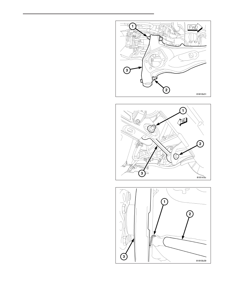
2. Position the upper control arm on the trailing link

(3) and install the bolt and nut (1) securing the arm
to the link. Tighten the mounting bolt nut to 95 N·m
(70 ft. lbs.).

3. Position the lower control arm on the trailing link

(3) and install the bolt and nut (2) securing the arm
to the link. Tighten the mounting bolt nut to 95 N·m
(70 ft. lbs.).

4. Install the bolt (2) securing the toe link to the trail-

ing link. To install the bolt it may be necessary to
flex the trailing link body mount bushing inward or
outward using an appropriate prying tool. Tighten
the mounting bolt to 95 N·m (70 ft. lbs.).

5. Insert the parking brake cable through the trailing

link from the inboard side.

6. Slide the parking brake cable (2) into the brake

support plate (3) with parking brake shoes.

7. Install the hair pin (1) securing the parking brake

cable (2) to the brake support plate (3).

PM

REAR SUSPENSION

2 - 53

8. Install the parking brake cable onto the lever on the

parking brake shoe.

9. If equipped, position the wheel speed sensor (3)

and install the screw (4) fastening the sensor to the
trailing link (2). Tighten the mounting screw to 18
N·m (13 ft. lbs.).

10. If equipped, position the wheel speed sensor (3)

and install the routing clip (1) fastening the sensor
to the trailing link (2).

11. Install the hub and bearing, then install the brake

rotor onto the wheel studs. (Refer to 2 - SUSPEN-
SION/REAR/HUB / BEARING - INSTALLATION)

12. Slide the disc brake caliper (2) and adapter (3)

assembly over brake rotor and brake support
plate.

13. Install the two bolts (1) securing disc brake caliper

adapter (3) to the brake support plate (4). Tighten
the mounting bolts to 105 N·m (77 ft. lbs.).

2 - 54

REAR SUSPENSION

PM

14. Position the brake tube on the trailing link insert-

ing the tube into the routing clip (2) and routing
bracket over the welded stud.

15. Install the nut (1) on the welded stud. Tighten the

nut to 15 N·m (11 ft. lbs.).

16. Position the brake flex hose (1) at the trailing link

(3) bracket and install the mounting screw (2).
Tighten the screw to 23 N·m (17 ft. lbs.).

17. Install tire and wheel assembly (1) (Refer to 22 -

TIRES/WHEELS - INSTALLATION). Install and
tighten wheel mounting nuts (3) to 135 N·m (100
ft. lbs.).

18. Lower the vehicle.

19. Perform wheel alignment as necessary. (Refer to

2 - SUSPENSION/WHEEL ALIGNMENT - STAN-
DARD PROCEDURE)

PM

REAR SUSPENSION

2 - 55

HUB / BEARING

DESCRIPTION

The rear wheel bearing and wheel mounting hub used on this vehicle are a one-piece sealed unit or hub and bear-
ing assembly. It is permanently lubricated when assembled and is sealed for life. There is no periodic lubrication or
maintenance recommended for these units.

The hub and bearing (5) is mounted to the trailing link
(1).

All vehicles have a magnetic encoder integrated into
the right rear hub and bearing for speed sense. Vehi-
cles equipped with antilock brakes have a magnetic
encoder integrated into both rear hub and bearings.
The encoder works with the rear wheel speed sensors
to provide wheel speed signal. The sensor mounts by
screw to the rear of the front-wheel-drive hub and
bearing while the sensor clips to the rear of the all-
wheel-drive hub and bearing.

The only serviceable components of the hub and
bearing are the wheel mounting studs pressed into the
hub.

DIAGNOSIS AND TESTING

HUB AND BEARING

NOTE: The wheel bearing is designed to last for the life of the vehicle and requires no type of periodic
maintenance.

The following procedure may be used for diagnosing the condition of the wheel bearing and hub.

1. Remove the wheel and tire assembly, disc brake caliper and brake rotor. (Refer to 5 - BRAKES/HYDRAULIC/

MECHANICAL/ROTORS - REMOVAL)

2. Rotate the wheel hub checking for resistance or roughness.

Any roughness or resistance to rotation may indicate dirt intrusion or a failed hub bearing. If the bearing exhibits any
of these conditions, the hub and bearing will require replacement. Do not attempt to disassemble the bearing for
repair. If the wheel bearing is disassembled for any reason, it must be replaced.

Damaged bearing seals and the resulting excessive grease loss may also require bearing replacement. Moderate
grease weapage from the bearing is considered normal and should not require replacement of the wheel bearing.

To diagnose a bent hub, measure hub runout. (Refer to 5 - BRAKES/HYDRAULIC/MECHANICAL/ROTORS - DIAG-
NOSIS AND TESTING)

REMOVAL

ALL-WHEEL-DRIVE

NOTE: Before proceeding, (Refer to 2 - SUSPENSION/REAR - WARNING).

1. Raise and support the vehicle. (Refer to LUBRICATION & MAINTENANCE/HOISTING - STANDARD PROCE-

DURE)

2 - 56

REAR SUSPENSION

PM


Content   ..  20  21  22  23   ..