Dodge Durango (DN). Manual - part 125


  Index      Dodge     Dodge Durango (DN) - service repair manual 2000 year


Search            


Content   ..  123  124  125  126   ..


Dodge Durango (DN). Manual - part 125


GEARSHIFT CABLE

REMOVAL

(1) Shift transmission into Park.
(2) Remove nuts retaining the shift cable housing

to the dash panel (Fig. 50).

(3) Disconnect cable at lower column lever and

feed cable through dash panel opening to underside
of vehicle (Fig. 51).

(4) Raise vehicle.
(5) Disengage cable eyelet at transmission shift

lever and pull cable adjuster out of mounting bracket
(Fig. 52). Remove old cable from vehicle.

INSTALLATION

(1) Snap the cable into the transmission bracket so

the retaining ears are engaged and connect cable end
fitting onto the manual control lever ball stud.

(2) Lower vehicle.
(3) Route cable through hole in dash panel. Seat

cable bracket to dash panel. Install retaining nuts to
cable housing bracket studs inside the vehicle at the
dash panel.

(4) Place the auto transmission manual shift con-

trol lever in “Park” detent (rearmost) position and
rotate prop shaft to ensure transmission is in park.

(5) Connect shift cable to shifter lever by snapping

cable retaining ears into shifter bracket and press
cable end fitting into lever.

(6) Check for proper operation of Park/Neutral

switch.

(7) If the gearshift cable is out of adjustment, refer

to Adjustments section.

DISASSEMBLY AND ASSEMBLY

TRANSMISSION

DISASSEMBLY

(1) Drain fluid from transmission.
(2) Clean exterior of transmission with suitable

solvent or pressure washer.

(3) Remove the torque converter from the trans-

mission.

(4) Remove the manual shift lever from the trans-

mission.

(5) Remove the input, output, and line pressure

sensors from the transmission case (Fig. 53).

(6) Inspect the ends of the sensors for debris,

which may indicate the nature of the transmission
failure.

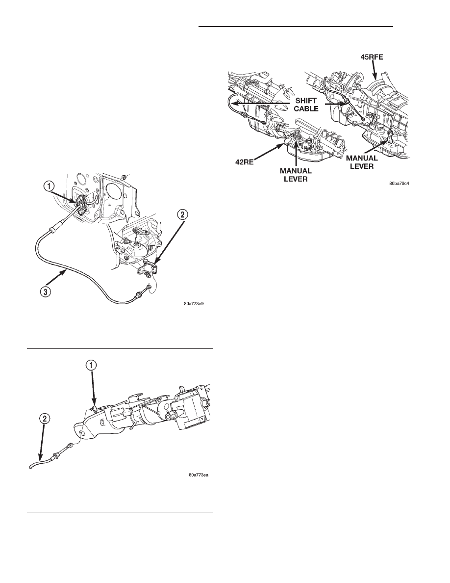
Fig. 50 Cable Mounting

1 – CABLE MOUNTING
2 – CABLE BRACKET AT TRANS.
3 – GEARSHIFT CABLE

Fig. 51 Cable at Gearshift Lever

1 – GEARSHIFT LEVER
2 – GEARSHIFT CABLE

Fig. 52 Shift Cable at the Transmission

21 - 366

45RFE AUTOMATIC TRANSMISSION

DN

REMOVAL AND INSTALLATION (Continued)

(7) Install Support Stand 8257 onto the transmis-

sion case (Fig. 54).

(8) Using Adapter 8266-1 from End-Play Tool Set

8266 and Dial Indicator C-3339, measure and record
the input shaft end-play (Fig. 55).

NOTE: When measuring the input shaft end-play,
two “stops” will be felt. When the input shaft is
pushed inward and the dial indicator zeroed, the
first

(

stop” felt when the input shaft is pulled out-

ward is the movement of the input shaft in the input
clutch housing hub. This value should not be
included in the end-play measured value and there-

fore must be recorded and subtracted from the dial
indicator reading.

(9) Remove the bolts holding the transmission

extension/adapter housing to the transmission case.

(10) Remove the extension/adapter housing from

the transmission case.

(11) Using Alignment Plate 8261, Adapter 8266-17

from End-Play Tool Set 8266 and Dial Indicator
C-3339, measure and record the output shaft end-
play (Fig. 56).

(12) Remove the bolts holding the transmission oil

pan to the transmission case.

(13) Remove the transmission oil pan from the

transmission case.

Fig. 53 Remove Input, Output, and Line Pressure

Sensors

Fig. 54 Install Support Stand—Tool 8257

Fig. 55 Measure Input Shaft End Play

Fig. 56 Measure Output Shaft End Play

DN

45RFE AUTOMATIC TRANSMISSION

21 - 367

DISASSEMBLY AND ASSEMBLY (Continued)

(14) Remove the primary oil filter and the oil

cooler filter (Fig. 57).

(15) Remove the cooler bypass valve.

(16) Remove the bolts holding the valve body to

the transmission case (Fig. 58).

(17) Remove the valve body from the transmission

case.

(18) Remove the outer snap-ring securing the

transmission front cover into the transmission case
(Fig. 59).

(19) Remove the inner snap-ring securing the

transmission front cover to the oil pump (Fig. 59).

(20) Reaching through a case opening in the valve

body area with a long blunted tool, remove the trans-
mission front cover from the transmission case.

(21) Remove the bolts holding the oil pump into

the transmission case (Fig. 60).

(22) Remove the oil pump. Hold inward on the

input shaft to prevent pulling the input clutch
assembly with the oil pump (Fig. 60).

(23) Remove the number 1 bearing from the input

clutch assembly (Fig. 61).

(24) Remove the input clutch assembly from the

transmission case (Fig. 61).

(25) Remove the number 5 bearing and selective

thrust plate from the input clutch assembly (Fig. 61),
or the 4C clutch retainer/bulkhead.

Fig. 57 Remove Primary Oil and Cooler Filters

Fig. 58 Remove Valve Body Assembly

Fig. 59 Remove Transmission Front Cover

Fig. 60 Remove Oil Pump

21 - 368

45RFE AUTOMATIC TRANSMISSION

DN

DISASSEMBLY AND ASSEMBLY (Continued)

(26) Remove

the

4C

clutch

retainer/bulkhead

tapered snap-ring from the transmission case (Fig.
62).

(27) Remove the 4C clutch retainer/bulkhead from

the transmission case (Fig. 62).

(28) Remove the front 2C clutch pack snap-ring

from the transmission case (Fig. 63).

(29) Remove the 2C clutch pack from the transmis-

sion case (Fig. 63).

(30) Remove the rear selective plate and number 6

bearing from the reaction annulus (Fig. 64).

(31) Remove the reaction annulus from the reac-

tion planetary carrier (Fig. 64).

(32) Remove the number 7 bearing (Fig. 64).
(33) Remove the reaction sun gear (Fig. 64).
(34) Remove the number 8 bearing from the reac-

tion planetary carrier (Fig. 64).

(35) Remove the reaction planetary carrier (Fig.

64). Note that this planetary gear set has three pin-
ion gears.

(36) Remove the number 9 bearing from the

reverse planetary gear set (Fig. 64).

(37) Remove the snap-ring holding the park sprag

gear onto the output shaft (Fig. 65).

(38) Remove the park sprag gear from the output

shaft (Fig. 66).

Fig. 61 Remove Input Clutch Assembly

Fig. 62 Remove 4C Clutch Retainer/Bulkhead

Fig. 63 Remove 2C Clutch Pack

DN

45RFE AUTOMATIC TRANSMISSION

21 - 369

DISASSEMBLY AND ASSEMBLY (Continued)


Content   ..  123  124  125  126   ..