Dodge Durango (DN). Manual - part 123


  Index      Dodge     Dodge Durango (DN) - service repair manual 2000 year


Search            


Content   ..  121  122  123  124   ..


Dodge Durango (DN). Manual - part 123


REMOVAL

(1) Hoist and support vehicle on safety stands.
(2) Place a large diameter shallow drain pan

beneath the transmission pan.

(3) Remove bolts holding front and sides of pan to

transmission.

(4) Loosen bolts holding rear of pan to transmis-

sion.

(5) Slowly separate front of pan away from trans-

mission allowing the fluid to drain into drain pan.

(6) Hold up pan and remove remaining bolt hold-

ing pan to transmission.

(7) While holding pan level, lower pan away from

transmission.

(8) Pour remaining fluid in pan into drain pan.
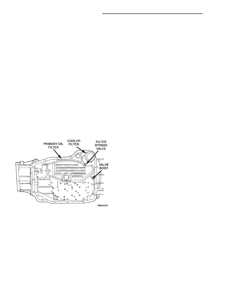
(9) Remove screws holding filter to valve body

(Fig. 36).

(10) Separate filter from valve body and oil pump

and pour fluid in filter into drain pan.

(11) Remove and discard the oil filter seal from the

bottom of the oil pump.

(12) Using Oil Filter Wrench 8321, remove the

cooler return filter from the transmission.

(13) Dispose of used trans fluid and filter properly.

INSPECTION

Inspect bottom of pan and magnet for excessive

amounts of metal. A light coating of clutch material
on the bottom of the pan does not indicate a problem
unless accompanied by a slipping condition or shift
lag. If fluid and pan are contaminated with excessive
amounts or debris, refer to the diagnosis section of
this group.

CLEANING

(1) Using a suitable solvent, clean pan and mag-

net.

(2) Using a suitable gasket scraper, clean original

sealing material from surface of transmission case
and the transmission pan.

INSTALLATION

(1) Install a new oil filter seal into the bottom of

the oi pump.

NOTE: Do not attempt to install the seal onto the
oil filter first and then into the oil pump. An unsat-
isfactory seal between the oil pump and filter will
result, allowing air to be drawn into the pump.

(2) Place replacement filter in position on valve

body and into the oil pump.

(3) Install screws to hold filter to valve body (Fig.

36). Tighten screws to 4.5 N·m (40 in. lbs.) torque.

(4) Install new cooler return filter onto the trans-

mission. Torque the filter to 14.12 N·m (125 in.lbs.).

(5) Place bead of Mopar

t RTV sealant onto the

transmission case sealing surface.

(6) Place pan in position on transmission.
(7) Install screws to hold pan to transmission.

Tighten bolts to 11.8 N·m (105 in. lbs.) torque.

(8) Lower

vehicle

and

fill

transmission

with

Mopar

t ATF Plus 3, type 7176 fluid.

TRANSMISSION FILL PROCEDURE

To avoid overfilling transmission after a fluid

change or overhaul, perform the following procedure:

(1) Remove dipstick and insert clean funnel in

transmission fill tube.

(2) Add following initial quantity of Mopar

t ATF

Plus 3 to transmission:

(a) If only fluid and filter were changed, add 10

pints (5 quarts) of ATF Plus 3 to transmission.

(b) If transmission was completely overhauled,

torque converter was replaced or drained, and
cooler was flushed, add 24 pints (12 quarts) of
ATF Plus 3 to transmission.
(3) Refer to the Fluid Level Check information in

this group for the proper fill procedures.

OIL PUMP VOLUME CHECK

Measuring the oil pump output volume will deter-

mine if sufficient oil flow to the transmission oil
cooler exists, and whether or not an internal trans-
mission failure is present.

Verify that the transmission fluid is at the proper

level. Refer to the Fluid Level Check procedure in
this section. If necessary, fill the transmission to the
proper level with Mopar

t ATF+3, type 7176, Auto-

matic Transmission Fluid.

(1) Disconnect the To cooler line at the cooler

inlet and place a collecting container under the dis-
connected line.

Fig. 36 Transmission Filters

21 - 358

45RFE AUTOMATIC TRANSMISSION

DN

SERVICE PROCEDURES (Continued)

CAUTION: With the fluid set at the proper level,
fluid collection should not exceed (1) quart or inter-
nal damage to the transmission may occur.

(2) Run the engine at curb idle speed, with the

shift selector in neutral.

(3) If one quart of transmission fluid is collected in

the container in 20 seconds or less, oil pump flow vol-
ume is within acceptable limits. If fluid flow is inter-
mittent, or it takes more than 20 seconds to collect
one quart of fluid, refer to the Hydraulic Pressure
tests in this section for further diagnosis.

(4) Re-connect the To cooler line to the transmis-

sion cooler inlet.

(5) Refill the transmission to proper level.

FLUSHING COOLERS AND TUBES

When a transmission failure has contaminated the

fluid, the oil cooler(s) must be flushed. The torque
converter must also be replaced. This will insure that
metal particles or sludged oil are not later trans-
ferred back into the reconditioned (or replaced) trans-
mission.

The only recommended procedure for flushing cool-

ers and lines is to use Tool 6906A Cooler Flusher.

WARNING: WEAR PROTECTIVE EYEWEAR THAT
MEETS THE REQUIREMENTS OF OSHA AND ANSI
Z87.1–1968. WEAR STANDARD INDUSTRIAL RUB-
BER GLOVES.

KEEP LIGHTED CIGARETTES, SPARKS, FLAMES,

AND OTHER IGNITION SOURCES AWAY FROM THE
AREA TO PREVENT THE IGNITION OF COMBUSTI-
BLE LIQUIDS AND GASES. KEEP A CLASS (B) FIRE
EXTINGUISHER

IN

THE

AREA

WHERE

THE

FLUSHER WILL BE USED.

KEEP THE AREA WELL VENTILATED.
DO NOT LET FLUSHING SOLVENT COME IN CON-

TACT WITH YOUR EYES OR SKIN: IF EYE CONTAM-
INATION OCCURS, FLUSH EYES WITH WATER FOR
15 TO 20 SECONDS. REMOVE CONTAMINATED
CLOTHING AND WASH AFFECTED SKIN WITH
SOAP AND WATER. SEEK MEDICAL ATTENTION.

COOLER FLUSH USING TOOL 6906A

(1) Remove cover plate filler plug on Tool 6906A.

Fill reservoir 1/2 to 3/4 full of fresh flushing solution.
Flushing solvents are petroleum based solutions gen-
erally used to clean automatic transmission compo-
nents. DO NOT use solvents containing acids, water,
gasoline, or any other corrosive liquids.

(2) Reinstall filler plug on Tool 6906A.
(3) Verify pump power switch is turned OFF. Con-

nect red alligator clip to positive (+) battery post.
Connect black (-) alligator clip to a good ground.

(4) Disconnect the cooler lines at the transmission.

NOTE: When

flushing

transmission

cooler

and

lines, ALWAYS reverse flush.

(5) Connect the BLUE pressure line to the OUT-

LET (From) cooler line.

(6) Connect the CLEAR return line to the INLET

(To) cooler line

(7) Turn pump ON for two to three minutes to

flush cooler(s) and lines.

(8) Turn pump OFF.
(9) Disconnect CLEAR suction line from reservoir

at cover plate. Disconnect CLEAR return line at
cover plate, and place it in a drain pan.

(10) Turn pump ON for 30 seconds to purge flush-

ing solution from cooler and lines. Turn pump OFF.

(11) Place CLEAR suction line into a one quart

container of Mopar

t ATF Plus 3, type 7176 automatic

transmission fluid.

(12) Turn pump ON until all transmission fluid is

removed from the one quart container and lines. This
purges any residual cleaning solvent from the trans-
mission cooler and lines. Turn pump OFF.

(13) Disconnect alligator clips from battery. Recon-

nect flusher lines to cover plate, and remove flushing
adapters from cooler lines.

TRANSMISSION QUICK LEARN PROCEDURE

The quick learn procedure requires the use of the

DRB scan tool.

This program allows the electronic transmission

system to recalibrate itself. This will provide the best
possible transmission operation. The quick learn pro-
cedure should be performed if any of the following
procedures are performed:

• Transmission Assembly Replacement

• Transmission Control Module Replacement

• Solenoid Pack Replacement

• Clutch Plate and/or Seal Replacement

• Valve Body Replacement or Recondition
To perform the Quick Learn Procedure, the follow-

ing conditions must be met:

• The brakes must be applied

• The engine speed must be above 500 rpm

• The throttle angle (TPS) must be less than 3

degrees

• The shift lever position must stay until

prompted to shift to overdrive

• The shift lever position must stay in overdrive

after the Shift to Overdrive prompt until the DRB
indicates the procedure is complete

• The calculated oil temperature must be above

60° and below 200°

ALUMINUM THREAD REPAIR

Damaged or worn threads in the aluminum trans-

mission case and valve body can be repaired by the

DN

45RFE AUTOMATIC TRANSMISSION

21 - 359

SERVICE PROCEDURES (Continued)

use of Heli-Coils, or equivalent. This repair consists
of drilling out the worn-out damaged threads. Then
tap the hole with a special Heli-Coil tap, or equiva-
lent, and installing a Heli-Coil insert, or equivalent,
into the hole. This brings the hole back to its original
thread size.

Heli-Coil, or equivalent, tools and inserts are

readily available from most automotive parts suppli-
ers.

REMOVAL AND INSTALLATION

INPUT SPEED SENSOR

REMOVAL

(1) Raise vehicle.
(2) Place a suitable fluid catch pan under the

transmission.

(3) Remove the wiring connector from the input

speed sensor (Fig. 37).

(4) Remove the bolt holding the input speed sensor

to the transmission case.

(5) Remove the input speed sensor from the trans-

mission case.

INSTALLATION

(1) Install the input speed sensor into the trans-

mission case.

(2) Install the bolt to hold the input speed sensor

into the transmission case. Tighten the bolt to 11.9
N·m (105 in.lbs.).

(3) Install the wiring connector onto the input

speed sensor

(4) Verify the transmission fluid level. Add fluid as

necessary.

(5) Lower vehicle.

OUTPUT SPEED SENSOR

REMOVAL

(1) Raise vehicle.
(2) Place a suitable fluid catch pan under the

transmission.

(3) Remove the wiring connector from the output

speed sensor (Fig. 38).

(4) Remove the bolt holding the output speed sen-

sor to the transmission case.

(5) Remove the output speed sensor from the

transmission case.

INSTALLATION

(1) Install the output speed sensor into the trans-

mission case.

(2) Install the bolt to hold the output speed sensor

into the transmission case. Tighten the bolt to 11.9
N·m (105 in.lbs.).

(3) Install the wiring connector onto the output

speed sensor

(4) Verify the transmission fluid level. Add fluid as

necessary.

(5) Lower vehicle.

LINE PRESSURE SENSOR

REMOVAL

(1) Raise vehicle.
(2) Place a suitable fluid catch pan under the

transmission.

(3) Remove the wiring connector from the line

pressure sensor (Fig. 39).

(4) Remove the bolt holding the line pressure sen-

sor to the transmission case.

Fig. 37 Input Speed Sensor

Fig. 38 Output Speed Sensor

21 - 360

45RFE AUTOMATIC TRANSMISSION

DN

SERVICE PROCEDURES (Continued)

(5) Remove the line pressure sensor from the

transmission case.

INSTALLATION

(1) Install the line pressure sensor into the trans-

mission case.

(2) Install the bolt to hold the line pressure sensor

into the transmission case. Tighten the bolt to 11.9
N·m (105 in.lbs.).

(3) Install the wiring connector onto the line pres-

sure sensor

(4) Verify the transmission fluid level. Add fluid as

necessary.

(5) Lower vehicle.

VALVE BODY

The valve body can be removed for service without

having to remove the transmission assembly.

The valve body can be disassembled for cleaning

and inspection of the individual components. Refer to
Disassembly and Assembly section for proper proce-
dures.

REMOVAL

(1) Shift transmission into PARK.
(2) Raise vehicle.
(3) Remove any necessary skid plates. Refer to

Group 13, Frame and Bumpers, for the appropriate
procedures.

(4) Disconnect wires at the solenoid and pressure

switch assembly connector.

(5) Position drain pan under transmission oil pan.
(6) Remove transmission oil pan.
(7) Remove the primary oil filter from valve body.
(8) Remove bolts attaching valve body to transmis-

sion case (Fig. 40).

(9) Lower the valve body and work the electrical

connector out of transmission case.

(10) Separate the valve body from the transmis-

sion.

INSTALLATION

(1) Check condition of seals on valve body and the

solenoid and pressure switch assembly. Replace seals
if cut or worn.

(2) Place TRS selector plate in the PARK position.
(3) Place the transmission in the PARK position.
(4) Lubricate seal on the solenoid and pressure

switch assembly connector with petroleum jelly.

(5) Position valve body in transmission and align

the manual lever on the valve body to the pin on the
transmission manual shift lever.

(6) Seat valve body in case and install one or two

bolts to hold valve body in place.

(7) Tighten valve body bolts alternately and evenly

to 12 N·m (105 in. lbs.) torque.

(8) Install new fluid filter on valve body. Tighten

filter screws to 4.5 N·m (40 in. lbs.) torque.

(9) Connect the solenoid and pressure switch

assembly connector.

(10) Install oil pan. Tighten pan bolts to 12 N·m

(105 in. lbs.) torque.

(11) Install any skid plates removed previously.

Refer to Group 13, Frame and Bumpers, for the
appropriate procedures.

(12) Lower vehicle and fill transmission with

Mopar

t ATF Plus 3, type 7176 fluid.

(13) Check and adjust gearshift cable, if necessary.

Fig. 39 Line Pressure Sensor

Fig. 40 Valve Body Bolts

DN

45RFE AUTOMATIC TRANSMISSION

21 - 361

REMOVAL AND INSTALLATION (Continued)


Content   ..  121  122  123  124   ..