Dodge Durango (DN). Manual - part 121


  Index      Dodge     Dodge Durango (DN) - service repair manual 2000 year


Search            


Content   ..  119  120  121  122   ..


Dodge Durango (DN). Manual - part 121


OPERATION

This battery voltage is necessary to retain adaptive

learn values in the TCM’s RAM (Random Access
Memory). When the battery (B+) is disconnected, this
memory is lost. When the battery (B+) is restored,
this memory loss is detected by the TCM and a Diag-
nostic Trouble Code (DTC) is set.

TRANSMISSION CONTROL RELAY

DESCRIPTION

The relay is supplied fused B+ voltage, energized

by the TCM, and is used to supply power to the sole-
noid pack when the transmission is in normal oper-
ating mode.

OPERATION

When the relay is “off”, no power is supplied to the

solenoid pack and the transmission is in “limp-in”
mode. After a controller reset, the TCM energizes the
relay. Prior to this, the TCM verifies that the con-
tacts are open by checking for no voltage at the
switched battery terminals. After this is verified, the
voltage at the solenoid pack pressure switches is
checked. After the relay is energized, the TCM mon-
itors the terminals to verify that the voltage is
greater than 3 volts.

PRESSURE SWITCHES

DESCRIPTION

The pressure switches are located inside the sole-

noid and pressure switch assembly and are only ser-
viced by replacing the assembly.

OPERATION

The TCM relies on five pressure switches to moni-

tor fluid pressure in the L/R, 2C, 4C, UD, and OD
hydraulic circuits. The primary purpose of these
switches is to help the TCM detect when clutch cir-
cuit hydraulic failures occur. The switches close at 23
psi and open at 11 psi, and simply indicate whether
or not pressure exists. The switches are continuously
monitored by the TCM for the correct states (open or
closed) in each gear as shown in the following chart:

A Diagnostic Trouble Code (DTC) will set if the

TCM senses any switch open or closed at the wrong
time in a given gear.

INPUT AND OUTPUT SPEED SENSORS

DESCRIPTION

The Input and Output Speed Sensors are two-wire

magnetic pickup devices that generate AC signals as
rotation occurs. They are mounted in the left side of
the transmission case and are considered primary
inputs to the Transmission Control Module (TCM).

OPERATION

The Input Speed Sensor provides information on

how fast the input shaft is rotating. As the teeth of
the input clutch hub pass by the sensor coil, an AC
voltage is generated and sent to the TCM. The TCM
interprets this information as input shaft rpm.

The Output Speed Sensor generates an AC signal

in a similar fashion, though its coil is excited by rota-
tion of the rear planetary carrier lugs. The TCM
interprets this information as output shaft rpm.

The TCM compares the input and output speed

signals to determine the following:

• Transmission gear ratio

• Speed ratio error detection

• CVI calculation
The TCM also compares the input speed signal and

the engine speed signal to determine the following:

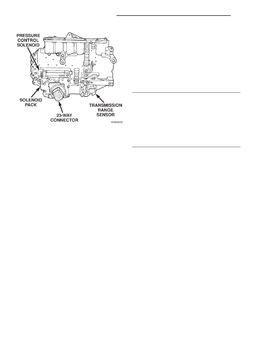
Fig. 29 SOLENOID AND PRESSURE SWITCH

ASSEMBLY

GEAR

L/R

2C

4C

UD

OD

R

OP

OP

OP

OP

OP

P/N

CL

OP

OP

OP

OP

1ST

CL*

OP

OP

CL

OP

2ND

OP

CL

OP

CL

OP

2ND

PRIME

OP

OP

CL

CL

OP

D

OP

OP

OP

CL

CL

OD

OP

OP

CL

OP

CL

*L/R is closed if output speed is below 100 rpm in

Drive and Manual 2. L/R is open in Manual 1.

21 - 350

45RFE AUTOMATIC TRANSMISSION

DN

DESCRIPTION AND OPERATION (Continued)

• Torque converter clutch slippage

• Torque converter element speed ratio

LINE PRESSURE CONTROL

DESCRIPTION

The TCM utilizes a closed-loop system to control

transmission line pressure. The system contains a
variable force style solenoid, the Pressure Control
Solenoid, mounted on the side of the solenoid and
pressure switch assembly. The solenoid is duty cycle
controlled by the TCM to vent the unnecessary line
pressure supplied by the oil pump back to the sump.
The system also contains a variable pressure style
sensor, the Line Pressure Sensor, which is a direct
input to the TCM. The line pressure solenoid moni-
tors the transmission line pressure and completes the
feedback loop to the TCM. The TCM uses this infor-
mation to adjust its control of the pressure control
solenoid to achieve the desired line pressure.

OPERATION

The TCM calculates the desired line pressure

based upon inputs from the transmission and engine.
The TCM calculates the torque input to the trans-
mission and uses that information as the primary
input to the calculation. The line pressure is set to a
predetermined value during shifts and when the
transmission is in the PARK and NEUTRAL posi-
tions. This is done to ensure consistent shift quality.
During all other operation, the actual line pressure is
compared to the desired line pressure and adjust-
ments are made to the pressure control solenoid duty
cycle.

THROTTLE POSITION SENSOR

OPERATION

The Transmission Control Module (TCM) receives

the throttle position signal and its ground from the
Throttle Position Sensor (TPS). The TPS has a 5 volt
pull up supplied by the engine controller. The throt-
tle signal is checked by the TCM for out-of-range as
well as intermittence (excessive signal changes).

TRANSMISSION RANGE SENSOR

DESCRIPTION

The Transmission Range Sensor (TRS) is mounted

to the top of the valve body inside the transmission.

The Transmission Range Sensor (TRS) has six

switch contacts that:

• Determine shift lever position

• Supply ground to the Starter Relay in Park and

Neutral only.

• Supply ground to the TCM for backup lamp con-

trol in Reverse only.

The TRS also has an integrated temperature sen-

sor (thermistor) that communicates transmission
temperature to the TCM and PCM.

OPERATION

The Transmission Range Sensor (TRS) communi-

cates shift lever position to the TCM as a combina-
tion of open and closed switches. Each shift lever
position has an assigned combination of switch states
(open/closed) that the TCM receives from four sense
circuits. The TCM interprets this information and
determines the appropriate transmission gear posi-
tion and shift schedule.

There are many possible combinations of open and

closed switches (codes). Seven of these possible codes
are related to gear position and five are recognized
as “between gear” codes. This results in many codes
which

should

never

occur.

These

are

called

“invalid” codes. An invalid code will result in a DTC,
and the TCM will then determine the shift lever
position based on pressure switch data. This allows
reasonably normal transmission operation with a
TRS failure.

TRANSMISSION TEMPERATURE SENSOR

DESCRIPTION

The transmission temperature sensor is a ther-

mistor that is integral to the Transmission Range
Sensor (TRS).

OPERATION

The transmission temperature sensor is used by

the TCM to sense the temperature of the fluid in the
sump. Since fluid temperature can affect transmis-
sion shift quality and convertor lock up, the TCM

GEAR

C5

C4

C3

C2

C1

Park

CL

OP

OP

CL

CL

Temp 1

CL

OP

OP

CL

OP

Reverse

OP

OP

OP

CL

OP

Temp 2

OP

OP

CL

CL

OP

Neutral 1

OP

OP

CL

CL

CL

Neutral 2

OP

CL

CL

CL

CL

Temp 3

OP

CL

CL

CL

OP

Drive

OP

CL

CL

OP

OP

Temp 4

OP

CL

OP

OP

OP

Manual 2

CL

CL

OP

OP

OP

Temp 5

CL

OP

OP

OP

OP

Manual 1

CL

OP

CL

OP

OP

DN

45RFE AUTOMATIC TRANSMISSION

21 - 351

DESCRIPTION AND OPERATION (Continued)

requires this information to determine which shift
schedule to operate in.

Calculated Temperature

A failure in the temperature sensor or circuit will

result in calculated temperature being substituted for
actual temperature. Calculated temperature is a pre-
dicted fluid temperature which is calculated from a
combination of inputs:

• Battery (ambient) temperature

• Engine coolant temperature

• In-gear run time since start-up

SOLENOIDS

DESCRIPTION

Solenoids are used to control the L/R, 2C, 4C, OD,

and UD friction elements. The reverse clutch is con-
trolled by line pressure and the position of the man-
ual valve in the valve body. All the solenoids are
contained within the Solenoid and Pressure Switch
Assembly. The solenoid and pressure switch assembly
contains one additional solenoid, Multi-Select (MS),
which serves primarily to provide 2nd and 3rd gear
limp-in operation.

OPERATION

The solenoids receive electrical power from the

Transmission Control Relay through a single wire.
The TCM energizes or operates the solenoids individ-
ually by grounding the return wire of the solenoid as
necessary. When a solenoid is energized, the solenoid
valve shifts, and a fluid passage is opened or closed
(vented or applied), depending on its default operat-
ing state. The result is an apply or release of a fric-
tional element.

The MS and UD solenoids are normally applied to

allow transmission limp-in in the event of an electri-
cal failure.

The continuity of the solenoids and circuits are

periodically tested. Each solenoid is turned on or off
depending on its current state. An inductive spike
should be detected by the TCM during this test. If no
spike is detected, the circuit is tested again to verify
the failure. In addition to the periodic testing, the
solenoid circuits are tested if a speed ratio or pres-
sure switch error occurs.

SOLENOID SWITCH VALVE

DESCRIPTION

The Solenoid Switch Valve (SSV) is located in the

valve body controls the direction of the transmission
fluid when the L/R-TCC solenoid is energized.

OPERATION

The Solenoid Switch Valve controls line pressure

from the LR-TCC solenoid. In 1st gear, the SSV will
be in the downshifted position, thus directing fluid to
the L/R clutch circuit. In 2nd, 3rd, and 4th, it will be
in the upshifted position and directs the fluid into
the torque converter clutch (TCC) circuit.

When shifting into 1st gear, a special hydraulic

sequence is performed to ensure SSV movement into
the downshifted position. The L/R pressure switch is
monitored to confirm SSV movement. If the move-
ment is not confirmed (the L/R pressure switch does
not close), 2nd gear is substituted for 1st. A DTC will
be set after three unsuccessful attempts are made to
get into 1st gear in one given key start.

DIAGNOSIS AND TESTING

EFFECTS OF INCORRECT FLUID LEVEL

A low fluid level allows the pump to take in air

along with the fluid. Air in the fluid will cause fluid
pressures to be low and develop slower than normal.
If the transmission is overfilled, the gears churn the
fluid into foam. This aerates the fluid and causing
the same conditions occurring with a low level. In
either case, air bubbles cause fluid overheating, oxi-
dation and varnish buildup which interferes with
valve, clutch and servo operation. Foaming also
causes fluid expansion which can result in fluid over-
flow from the transmission vent or fill tube. Fluid
overflow can easily be mistaken for a leak if inspec-
tion is not careful.

CAUSES OF BURNT FLUID

Burnt, discolored fluid is a result of overheating

which has two primary causes.

(1) A result of restricted fluid flow through the

main and/or auxiliary cooler. This condition is usu-
ally the result of a faulty or damaged main/auxiliary
cooler, or severe restrictions in the coolers and lines
caused by debris or kinked lines.

(2) Heavy duty operation with a vehicle not prop-

erly equipped for this type of operation. Trailer tow-
ing or similar high load operation will overheat the
transmission

fluid

if

the

vehicle

is

improperly

equipped. Such vehicles should have an auxiliary
transmission fluid cooler, a heavy duty cooling sys-
tem, and the engine/axle ratio combination needed to
handle heavy loads.

FLUID CONTAMINATION

Transmission fluid contamination is generally a

result of:

• adding incorrect fluid

21 - 352

45RFE AUTOMATIC TRANSMISSION

DN

DESCRIPTION AND OPERATION (Continued)

• failure to clean dipstick and fill tube when

checking level

• engine coolant entering the fluid

• internal failure that generates debris

• overheat that generates sludge (fluid break-

down)

• failure to reverse flush cooler and lines after

repair

• failure to replace contaminated converter after

repair

The use of non recommended fluids can result in

transmission failure. The usual results are erratic
shifts, slippage, abnormal wear and eventual failure
due to fluid breakdown and sludge formation. Avoid
this condition by using recommended fluids only.

The dipstick cap and fill tube should be wiped

clean before checking fluid level. Dirt, grease and
other foreign material on the cap and tube could fall
into the tube if not removed beforehand. Take the
time to wipe the cap and tube clean before withdraw-
ing the dipstick.

Engine coolant in the transmission fluid is gener-

ally caused by a cooler malfunction. The only remedy
is to replace the radiator as the cooler in the radiator
is not a serviceable part. If coolant has circulated
through the transmission for some time, an overhaul
may also be necessary; especially if shift problems
had developed.

The transmission cooler and lines should be

reverse flushed whenever a malfunction generates
sludge and/or debris. The torque converter should
also be replaced at the same time.

Failure to flush the cooler and lines will result in

recontamination. Flushing applies to auxiliary cool-
ers as well. The torque converter should also be
replaced whenever a failure generates sludge and
debris. This is necessary because normal converter
flushing procedures will not remove all contami-
nants.

45RFE AUTOMATIC TRANSMISSION GENERAL
DIAGNOSIS

CAUTION: Before attempting any repair on a 45RFE
automatic transmission, check for Diagnostic Trou-
ble Codes with the DRB scan tool.

Transmission malfunctions may be caused by these

general conditions:

• Poor engine performance

• Improper adjustments

• Hydraulic malfunctions

• Mechanical malfunctions

• Electronic malfunctions
Diagnosis of these problems should always begin

by checking the easily accessible variables: fluid level

and condition, gearshift cable adjustment. Then per-
form a road test to determine if the problem has been
corrected or if more diagnosis is necessary. If the
problem persists after the preliminary tests and cor-
rections are completed, hydraulic pressure checks
should be performed.

PRELIMINARY DIAGNOSIS

Two basic procedures are required. One procedure

for vehicles that are drivable and an alternate proce-
dure for disabled vehicles (will not back up or move
forward).

VEHICLE IS DRIVABLE

(1) Check for transmission fault codes using DRB

scan tool.

(2) Check fluid level and condition.
(3) Adjust gearshift cable if complaint was based

on delayed, erratic, or harsh shifts.

(4) Road test and note how transmission upshifts,

downshifts, and engages.

(5) Perform stall test if complaint is based on slug-

gish acceleration. Or, if abnormal throttle opening is
needed to maintain normal speeds with a properly
tuned engine.

(6) Perform hydraulic pressure test if shift prob-

lems were noted during road test.

(7) Perform air-pressure test to check clutch oper-

ation.

VEHICLE IS DISABLED

(1) Check fluid level and condition.
(2) Check for broken or disconnected gearshift

cable.

(3) Check for cracked, leaking cooler lines, or loose

or missing pressure-port plugs.

(4) Raise and support vehicle on safety stands,

start engine, shift transmission into gear, and note
following:

(a) If propeller shaft turns but wheels do not,

problem is with differential or axle shafts.

(b) If propeller shaft does not turn and transmis-

sion is noisy, stop engine. Remove oil pan, and
check for debris. If pan is clear, remove transmis-
sion and check for damaged driveplate, converter,
oil pump, or input shaft.

(c) If propeller shaft does not turn and transmis-

sion is not noisy, perform hydraulic-pressure test to
determine if problem is hydraulic or mechanical.

GEARSHIFT CABLE

(1) The shifter lever and gate positions should be

in alignment with all transmission PARK, NEU-
TRAL, and gear detent positions.

(2) Engine starts must be possible with shift lever

in PARK or NEUTRAL gate positions only. Engine

DN

45RFE AUTOMATIC TRANSMISSION

21 - 353

DIAGNOSIS AND TESTING (Continued)


Content   ..  119  120  121  122   ..