Dodge Durango (DN). Manual - part 126


  Index      Dodge     Dodge Durango (DN) - service repair manual 2000 year


Search            


Content   ..  124  125  126  127   ..


Dodge Durango (DN). Manual - part 126


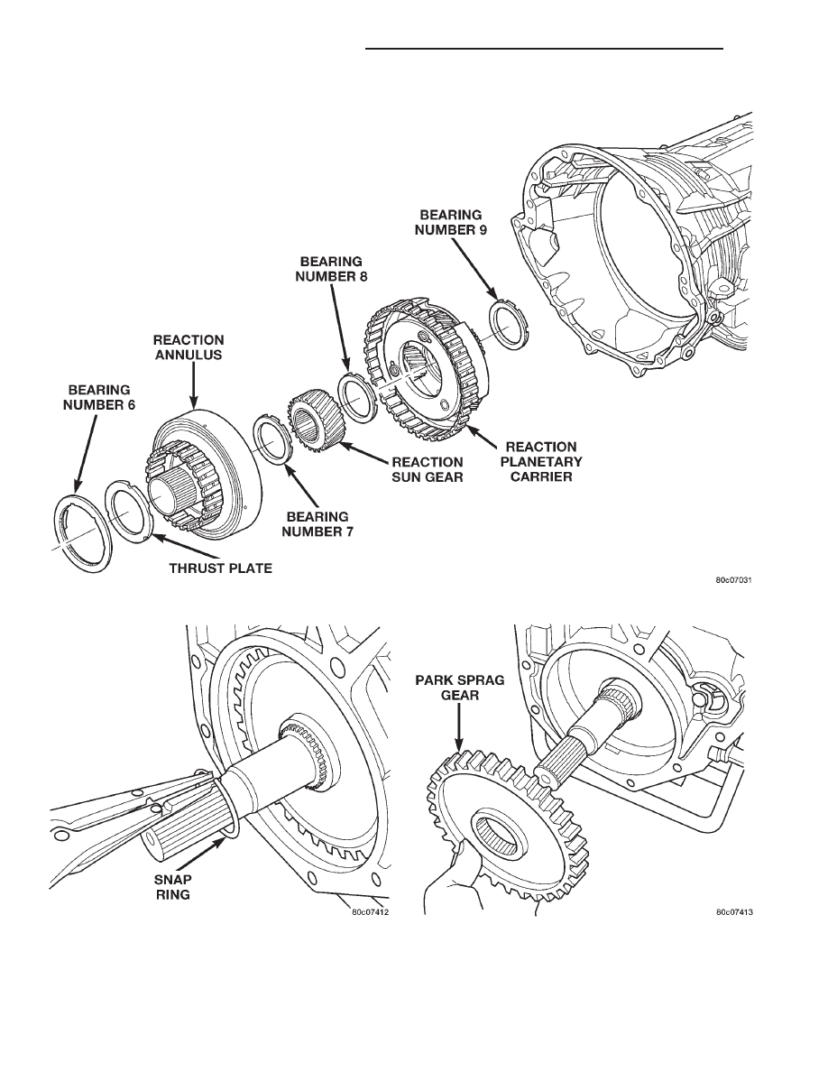
Fig. 64 Remove Reaction Annulus and Carrier

Fig. 65 Remove Park Sprag Snap Ring

Fig. 66 Remove Park Sprag Gear

21 - 370

45RFE AUTOMATIC TRANSMISSION

DN

DISASSEMBLY AND ASSEMBLY (Continued)

(39) Remove the input/reverse planetary assembly

(Fig. 67).

(40) Remove the number 12 bearing from the

input/reverse planetary assembly (Fig. 67).

(41) Remove the snap-ring holding the low/reverse

clutch retainer into the transmission case (Fig. 68).

(42) Remove the low/reverse clutch retainer from

the transmission case (Fig. 68).

(43) Remove the park pawl rod and e-clip (Fig. 69).
(44) Remove the park pawl rod guide snap-ring

(Fig. 69).

(45) Remove the park pawl rod guide (Fig. 69).
(46) Remove the park pawl pivot shaft, park pawl,

and spring (Fig. 69).

(47) Remove the manual selector shaft (Fig. 69).

(48) Remove the manual selector shaft seal.
(49) Remove the dipstick tube seal.

ASSEMBLY

(1) Clean and inspect all components. Replace any

components which show evidence of excessive wear
or scoring.

(2) Install the cooler filter bypass valve.
(3) Torque the bypass valve to specification. The

valve uses a tapered pipe thread and excessive
torque can damage the transmission case. Tighten
the cooler filter bypass valve to 11.3 N·m (100
in.lbs.).

(4) Install a new selector shaft seal using Seal

Installer 8253 (Fig. 70).

(5) Install the manual selector shaft and retaining

screw. Tighten the manual selector shaft retaining
screw to 28 N·m (250 in.lbs.).

(6) Install the park pawl, spring, and shaft (Fig.

69).

(7) Install the park rod and e-clip (Fig. 69).
(8) Install the park rod guide and snap-ring (Fig.

69).

(9) Install a new dipstick tube seal using Seal

Installer 8254 (Fig. 71).

NOTE: Before final assembly of transmission cen-
terline, the 2C/4C clutch components should be
installed into position and measured/adjusted as
follows:

Fig. 67 Remove Input/Reverse Planetary Assembly

Fig. 68 Remove Low/Reverse Clutch Retainer

Fig. 69 Manual Shaft/Park Lock Components

DN

45RFE AUTOMATIC TRANSMISSION

21 - 371

DISASSEMBLY AND ASSEMBLY (Continued)

(10) Install the 2C reaction plate into the trans-

mission case (Fig. 63). The reaction plate is selective
and directional. The plate must be installed with the
flat side toward the front.

(11) Install the 2C clutch pack into the transmis-

sion case (Fig. 63).

(12) Install the flat 2C clutch snap-ring into the

transmission case (Fig. 63).

(13) Install the 4C retainer/bulkhead into the

transmission case. Make sure that the oil feed holes
are pointing toward the valve body area.

(14) Install

the

4C

retainer/bulkhead

tapered

snap-ring into the transmission case. Make sure that
the open ends of the snap-ring are located in the case
opening toward the valve body area.

(15) Using a feeler gauge through the opening in

the rear of the transmission case, measure the 2C
clutch pack clearance between the 2C reaction plate

and the transmission case at four different points.
The average of these measurements is the 2C clutch
pack clearance. Adjust the clearance as necessary.
The correct clutch clearance is 0.533–1.27 mm
(0.021–0.050 in.). The reaction plate is selective.
Install the chosen reaction plate and re-measure the
clutch clearance to verify the selection.

(16) Remove the 4C retainer/bulkhead and all of

the 2C clutch components from the transmission
case.

(17) Install the low/reverse clutch assembly (Fig.

72). Make sure that the oil feed hole points toward
the valve body area and that the bleed orifice is
aligned with the notch in the rear of the transmis-
sion case.

(18) Install the snap-ring to hold the low/reverse

clutch retainer into the transmission case (Fig. 72).
The snap-ring is tapered and must be installed with
the tapered side forward. Once installed, verify that
the snap-ring is fully seated in the snap-ring groove.

(19) Air check the low/reverse clutch and verify

correct overrunning clutch operation.

(20) Install the reverse/input planetary assembly

through the low/reverse clutch assembly (Fig. 73).

(21) Install the number 12 bearing over the output

shaft of the rear planetary gear set and onto the low/
reverse clutch assembly. The flat side of the bearing
goes toward the clutch assembly.

(22) Install the park sprag onto the output shaft

(Fig. 74).

(23) Install the snap-ring to hold the park sprag

onto the output shaft (Fig. 75).

(24) Install the 2C reaction plate into the trans-

mission case (Fig. 76). The reaction plate is selective
and directional. The plate must be installed with the
flat side toward the front.

Fig. 70 Install Selector Shaft Seal Using Tool 8253

Fig. 71 Install Dipstick Tube Seal Using Tool 8254

Fig. 72 Install Low/Reverse Clutch Retainer

21 - 372

45RFE AUTOMATIC TRANSMISSION

DN

DISASSEMBLY AND ASSEMBLY (Continued)

(25) Install the 2C clutch pack into the transmis-

sion case (Fig. 76).

(26) Install the number 8 bearing inside the reac-

tion carrier with the round side against the plane-
tary carrier.

(27) Install the reaction planetary gear set and the

number 9 bearing into the transmission case (Fig.
77).

(28) Install the flat 2C clutch snap-ring into the

transmission case (Fig. 76).

(29) Install the reaction sun gear into the reaction

planetary gear set with the small shoulder facing the
front of the transmission (Fig. 77).

(30) Install the number 7 bearing onto the reaction

sun gear with the flat side against the sun gear (Fig.
77).

(31) Install the output shaft selective thrust plate

onto the reaction annulus with the oil grooves facing
the annulus gear and the tabs and notches aligned as
shown in (Fig. 78).

(32) Install the number 6 bearing against the out-

put shaft selective spacer with the flat side against
the spacer (Fig. 77).

(33) Install the reaction annulus into the reaction

planetary gear set (Fig. 77).

(34) Install the 4C retainer/bulkhead into the

transmission case. Make sure that the oil feed holes
are pointing toward the valve body area. Rotate the
reaction annulus during the installation of the 4C
retainer/bulkhead to ease installation.

(35) Install

the

4C

retainer/bulkhead

tapered

snap-ring into the transmission case (Fig. 79). Make

Fig. 73 Install Input/Reverse Planetary Assembly

Fig. 74 Install Park Sprag Gear

Fig. 75 Install Park Sprag Snap Ring

Fig. 76 Install 2C Clutch Pack

DN

45RFE AUTOMATIC TRANSMISSION

21 - 373

DISASSEMBLY AND ASSEMBLY (Continued)


Content   ..  124  125  126  127   ..