DAF CF65, CF75, CF85 Series . Manual - part 912


  Index      DAF     DAF CF65, CF75, CF85 Series - service repair manual


Search            


Content   ..  910  911  912  913   ..


DAF CF65, CF75, CF85 Series . Manual - part 912


©

 200423

2-33

Inspection and adjustment

BRAKE SYSTEM AND COMPONENTS

ΧΦ65/75/85 series

6

5

2.

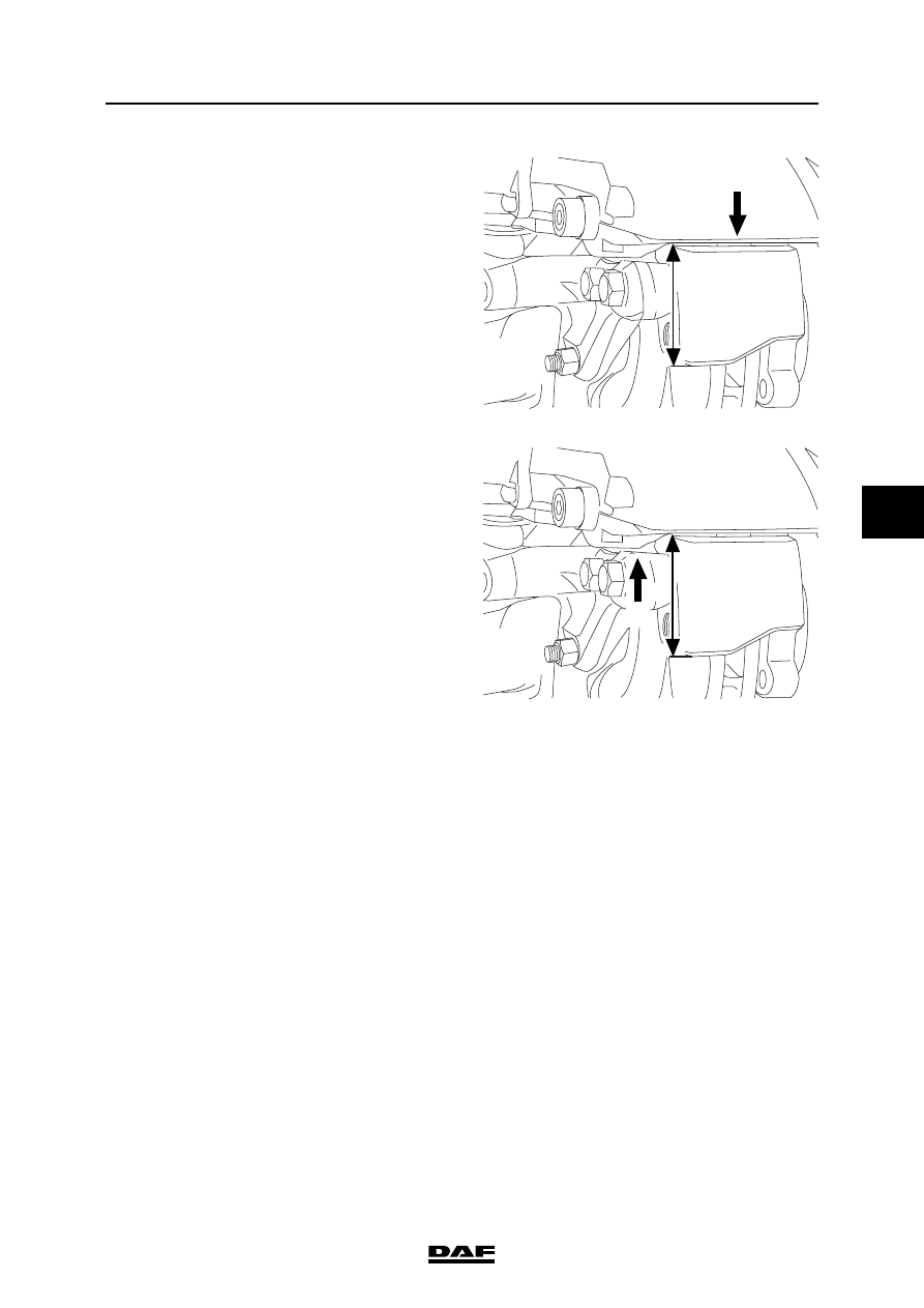
Push the brake calliper as far as possible 
towards the brake calliper support (C).

3.

Measure the distance "X".

4.

Push the reversed brake calliper as far as 
possible towards the brake calliper 
support (D).

5.

Measure the distance "Y".

6.

Calculate the difference between 
the measured distances, "Y" - "X" 
(see "Technical data").

7.

Fit the brake pads.

X

R600710

C

Y

R600711

D

BRAKE SYSTEM AND COMPONENTS

2-34

©

 200423

Inspection and adjustment

5

ΧΦ65/75/85 series

6

2.22 BRAKE ADJUSTMENT, DRUM BRAKE VERSION

Set the brakes by turning the hexagonal adjusting 
bolt clockwise.

Turn the adjusting bolt until the brake lining abuts 
the brake drum.
Then turn the adjusting bolt back (90

 - 120) 

until the bake lining is just free of the brake drum.

R600253

©

 200423

2-35

Inspection and adjustment

BRAKE SYSTEM AND COMPONENTS

ΧΦ65/75/85 series

6

5

2.23 BRAKE ADJUSTMENT, DISC BRAKE VERSION

1.

Position a feeler gauge between the rear 
of the brake pad and one of the thrust 
pieces of the brake calliper to check the play. 
Compare the measured value 
(see "Technical data").

2.

If the play is not correct, it needs to be 
adjusted. Remove the covering cap from 
the slack adjuster.

3.

Fit a ring spanner on the adapter and turn 
the hexagonal adjusting bolt together with 
the adapter anti-clockwise until there is 
ample clearance between the brake pads 
and the brake disc.

Note:
Never turn the hexagonal adjusting bolt 
without using an adapter. The adapter 
is a torque safety and will break off when the 
torque is too high. Without the use of an 
adapter the mechanics in the brake calliper 
may become damaged when the torque 
is too high, so that replacement of the brake 
calliper may be necessary.

4.

Position a feeler gauge with the correct 
thickness between the brake pad and the 
thrust piece of the adjuster with the 
hexagonal adjusting bolt. See "Technical 
data".

5.

Turn the hexagonal adjusting bolt clockwise 
with the ring spanner and the adapter until 
the feeler gauge just fits. Remove the feeler 
gauge.

6.

Apply the brake a number of times so that the 
play can set.

7.

Release the brake. Now it should be possible 
to turn the hub by hand.

8.

Position a feeler gauge between the 
rear of the brake pad and one of the thrust 
pieces of the brake calliper to check the play. 
Compare the measured value 
(see "Technical data").

9.

After the inspection, lightly grease the 
sealing cap and replace it on the slack 
adjuster. See "Technical data".

23

37

1

R600463

BRAKE SYSTEM AND COMPONENTS

2-36

©

 200423

Inspection and adjustment

5

ΧΦ65/75/85 series

6

2.24 INSPECTION, AIR TIGHTNESS

Air tightness
If the brake system of a vehicle has been charged 
to the maximum pressure, it should generally be 
possible to drive the vehicle away after a period 
of 16 hours of uninterrupted standstill, without 
first having to charge the brake system to 
sufficient operating pressure.
This implies a maximum pressure drop of approx. 
0.4 bar per hour at normal system pressure.

Note:
Always connect auxiliary consumers and 
accessories to circuit 4.


Content   ..  910  911  912  913   ..