DAF CF65, CF75, CF85 Series . Manual - part 901


  Index      DAF     DAF CF65, CF75, CF85 Series - service repair manual


Search            


Content   ..  899  900  901  902   ..


DAF CF65, CF75, CF85 Series . Manual - part 901


6

CF65/75/85 series

Description of components

OPERATION OF BRAKE COMPONENTS

2-39

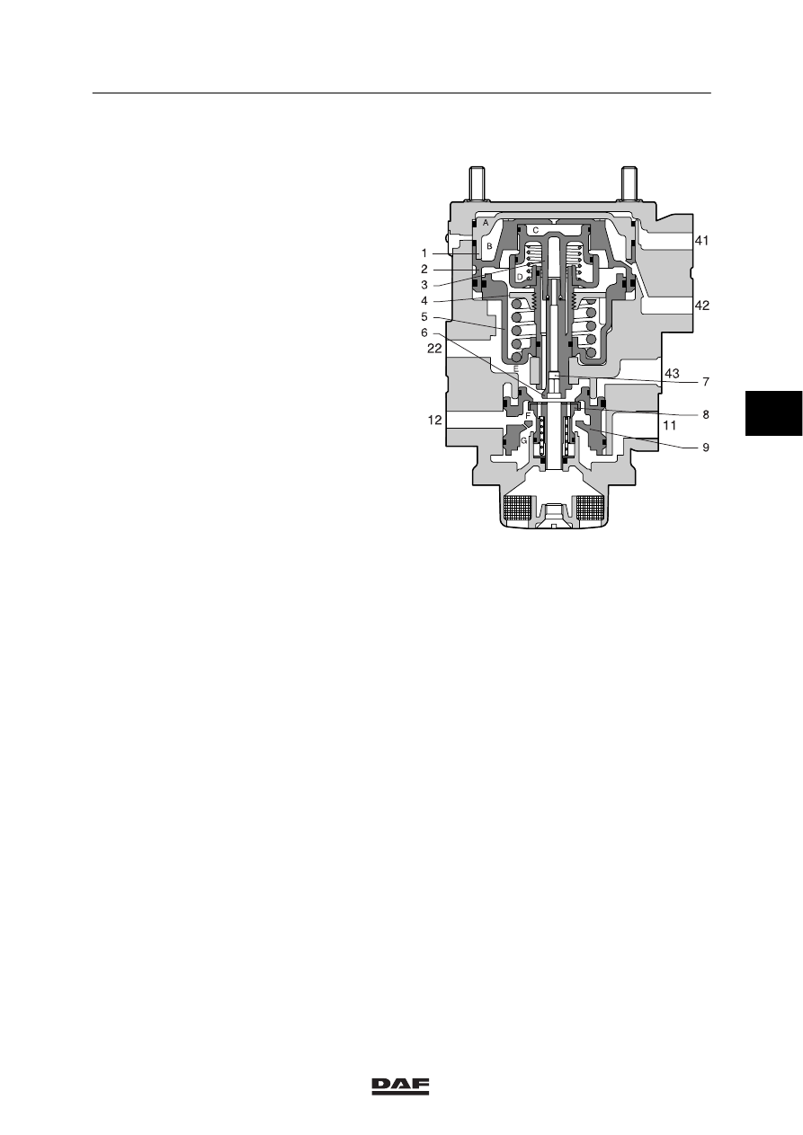
Brake pressure advance

Pressure build-up
If the foot brake valve is used to build up
pressure at connection points 41 and 42, the
output pressure at connection point 22 will also
move piston 5 upwards, closing valve 8.
There is now a state of balance between the
input pressure at connection point 41 and the
output pressure at connection point 22.

Change
If adjusting screw 6 is turned clockwise, for
example, spring retainer 4 will be moved
downwards, further compressing the spring
underneath it. Therefore, if the operating
pressure at connection points 41 and 42 remain
the same, a higher adjusting pressure will be
needed under piston 5. This adjusting pressure
is also on the yellow coupling head.

This increase of service pressure to the trailer
vehicle in relation to the brake pressure from the
truck is called brake pressure advance.
For the setting procedure, see “Inspection and
adjustment”.

R600340

4

ᓻ 200324

6

OPERATION OF BRAKE COMPONENTS

Description of components

CF65/75/85 series

2-40

Emergency brake
When the parking brake valve is moved into the
locking position, connection point 43 will be
gradually vented.
Piston 9 moves upwards and valve 8 is opened.
Depending on the drop in pressure at
connection point 43, a pressure build-up will
occur at connection point 22. When a pre-set
value has been reached, valve 8 will close so
that a state of equilibrium is achieved.

Parking brake
When the parking brake valve is in its maximum
position, i.e. the position at which the lever is
blocked, connection point 43 is vented. As a
consequence, there is still an output pressure at
connection 22.

Protection against breakage of service line
During braking pressure will be built up on
connection point 22. The air needed for this is
supplied from connection point 11.
If the service line is broken, pressure will not
build up in chamber E, which will cause piston 9
to move up and close against the bottom of
valve 8. The supply from connection point 11
stagnates, causing pressure to be delivered
from connection point 12.
The pressure in the reservoir pipe drops and the
trailer vehicle brakes are applied.

R600340

4

ᓻ 200324

6

CF65/75/85 series

Description of components

OPERATION OF BRAKE COMPONENTS

2-41

2.20 COUPLING HEAD

Application
With spring-loaded valve. Fitted in the
dual-circuit brake system of versions with trailer
connections.
If these automatic coupling heads are applied,
there is no need for an air cock.

Purpose
Connecting the air brake system of the tractive
unit with that of the trailer vehicle.

Operation
Spring-loaded valve 2 in the coupling head
ensures that the system is isolated from the
ambient air.
When coupling, turn the counter head until the
claws of the two heads rest against the stop
under the locking plates. This will prevent the
coupling head from disengaging spontaneously.
Because the two sealing rings (1) are pressed
against each other, the spring-loaded valve
remains open so that an air-tight connection is
achieved. When the heads are uncoupled, the
spring-loaded valve will seal off the pipe on the
tractive unit.
The coupling head is equipped with a safety
cam. This is to prevent different coupling heads
being coupled to one another.
If no trailer vehicle is hooked up, the cover of
the coupling head must be closed, to avoid
fouling.

R600101

2

1

2

1

4

ᓻ 200324

6

OPERATION OF BRAKE COMPONENTS

Description of components

CF65/75/85 series

2-42

2.21 AUTOMATIC BRAKE ADJUSTER

Purpose
The purpose of the automatic brake adjuster is
to automatically compensate for any excessive
play between the brake lining and the brake
drum caused by brake lining wear. As a result,
the cylinder travel during braking remains more
or less constant.

1.

Housing

2.

Bearing

3.

Pinion of overrunning clutch

4.

Spring of overrunning clutch

5.

Conical ring of overrunning clutch

6.

Worm shaft

7.

Pivot bearing

8.

Screw cap

9.

Gear

10. Rack
11.

Spring retainer

12. Spring
13. Screw cap
14. Control plate

Angle A: the angle corresponding to the basic
brake stroke.

Operation
Lining wear causes extra clearance between
lining and drum. This is adjusted during the
return stroke of the brake adjuster.
The brake cylinder stroke is composed of the
following three components:

-

the basic brake stroke, which corresponds
to the normal clearance between lining and
drum;

-

the additional stroke, which corresponds to
the additional clearance between lining and
drum due to lining wear;

-

the elastic stroke due to the elasticity of
drum, lining, shoes and brake camshaft.

1

2
3

4
5

6

7

8

10

10

12

13

B

A

14

R600017

4

ᓻ 200324


Content   ..  899  900  901  902   ..