DAF CF65, CF75, CF85 Series . Manual - part 900
6
CF65/75/85 series
Description of components
OPERATION OF BRAKE COMPONENTS
2-35
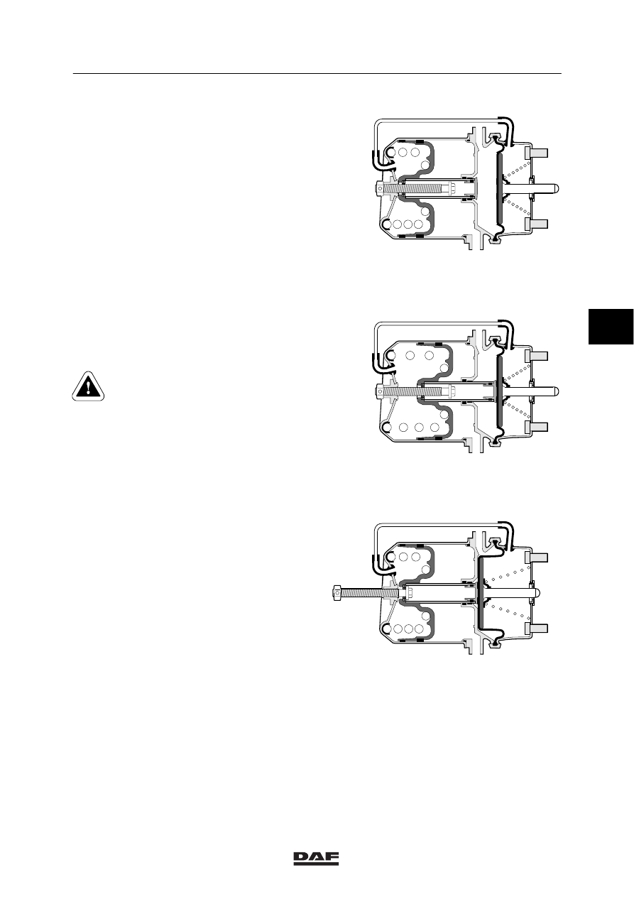
Parking brake
Connection point 12 is vented.
The powerful spring then forces the piston with
the piston tube against the diaphragm, so that
the push rod is forced outwards. Here, use is
made of the continuously available energy of the
compressed, powerful spring.
Release tool, spring brake cylinder with
unscrewable release bolt
If, due to a failure, no compressed air is
available in the spring brake cylinder, the vehicle
brakes are automatically applied.
But it must still be possible to tow the vehicle.
The spring brake cylinder is therefore fitted with
a release bolt at the rear. By turning this bolt
anticlockwise using a spanner, the powerful
spring will be compressed.
As the bolt is provided with a thrust bearing, the
torque required is not more than 20 - 40 Nm.
Do not use a pneumatic spanner for this
purpose.
Because the spring brakes have
been released mechanically, the
parking brake can no longer be
applied.
Once the failure has been remedied and
sufficient compressed air is available, the control
valve can be used to again admit air into the
spring brake cylinder.
The release bolt should then be screwed back in
with the spanner and tightened to the specified
torque. See “Technical data”. The pressure in
the spring brake cylinder circuit should be at
least 6.5 bar.
11
12
11
12
11
12
R600507
4
ᓻ 200324