DAF CF65, CF75, CF85 Series . Manual - part 898


  Index      DAF     DAF CF65, CF75, CF85 Series - service repair manual


Search            


Content   ..  896  897  898  899   ..


DAF CF65, CF75, CF85 Series . Manual - part 898


6

CF65/75/85 series

Description of components

OPERATION OF BRAKE COMPONENTS

2-27

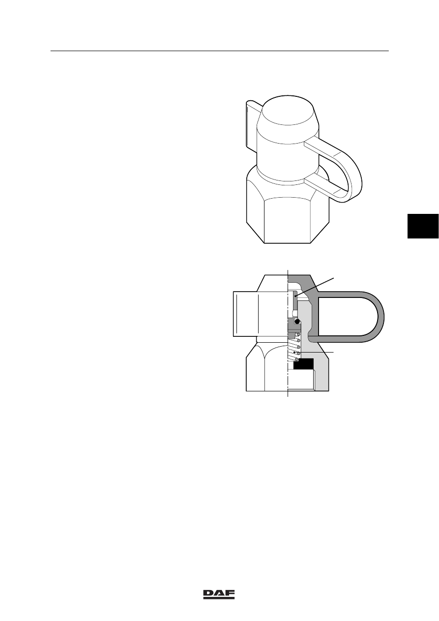
2.14 EMERGENCY FILLING/TEST CONNECTION

In various places in the brake system there are
test connections for carrying out inspections and
adjustments. A pipe leads from point 24 of the
air dryer to the rear left of the cab. There is a
test connection here that can be used as an
emergency filling/tyre pump connection.

Note:
With a leaf-sprung front axle this test connection
is on point 11 of the air dryer.

If a pipe is connected to the test connection,
screwing in the union will lift the spring-loaded
valve (A) from its seat, opening the supply. If the
union is removed, the valve is pushed onto its
seat by spring B, closing the supply.

A

B

R600495

4

ᓻ 200324

6

OPERATION OF BRAKE COMPONENTS

Description of components

CF65/75/85 series

2-28

2.15 BRAKE CYLINDER

Purpose
The purpose of the brake cylinder is to apply the
brake shoes or pads to the brake drum/disc.

Operation
When the foot brake valve is operated,
compressed air is admitted at the pressure side
of diaphragm 1. Diaphragm 1 and push rod 2
are pushed outwards against the pressure of the
spring. As a result, the brake shoes are forced
against the brake drum via a lever mechanism.
The air on the other side of the diaphragm can
escape via vent holes and the clearance around
the push rod.
When the brakes are released, coil spring 3 will
force the push rod and the diaphragm back to
their initial position.
When the brakes are released, the brake
cylinder will always draw in ambient air on the
non-pressure side. When the brakes are
released the push rod should return fully to its
initial position. The triggering pressure should
not exceed 0.5 bar.

R600505

2

1

3

R600506

4

ᓻ 200324

6

CF65/75/85 series

Description of components

OPERATION OF BRAKE COMPONENTS

2-29

2.16 PARKING BRAKE VALVE

PARKING BRAKE VALVE WITH

TRAILER CONNECTION AND TEST

POSITION

Purpose
The parking brake valve enables simultaneous,
controlled operation of both the parking brake
system of the truck and the trailer vehicle
brakes.

Operation
The parking brake valve has 3 positions:
1.

driving

2.

parking

3.

test

3

21

1

22

2
3

5

4

6

8

7

9

10

R600397

1

21

22

Driving
With the handle in the driving position, there is a
through connection in the valve for the supply
pressure (connection point 1) to the connection
points for spring brake cylinders 21 and trailer
vehicle 22. The vent is now closed.
The output pressure at connection points 21 and
22 is now approx. 8.5 bar (see graph).

Emergency braking
If the handle is pulled a little backwards against
the spring pressure, tappet 3 will move
downwards via eccentric 2. The chamber at
connection point 21 can now be vented and as a
result the pressure at connection point 21 will
drop. Via the bore in valve 10 the pressure at
connection point 22 will also drop. Spring 4
forces piston 5 down until valve 6 comes into
contact with the seal collar of tappet 3. A state
of equilibrium has now been achieved.

When the handle is moved against stop 7, the
vent will remain open, so that the spring brakes
and the trailer vehicle brakes will be applied to
their maximum (max. emergency-brake
position).

4

ᓻ 200324

6

OPERATION OF BRAKE COMPONENTS

Description of components

CF65/75/85 series

2-30

Parking
When the handle is pulled past stop 7, it is
locked in position.
Connection points 21 and 22 will remain
pressureless, so that the spring brakes and the
trailer vehicle brakes are still applied to their
maximum.

Test
When the handle is moved beyond the parking
position, cam 8 will move tappet 9 downwards,
causing the bore in valve 10 to be closed and
the valve to be lifted from its seat.
The supply pressure can now be passed to
connection point 22, via a bore in piston 5. As a
result, the trailer vehicle brakes will be released.
Connection point 21 remains vented, so that the
spring brakes keep the parking brake shoes
applied.
The combination is now braked only by the force
exerted by the spring brake cylinders on the
truck. It can now be checked whether the
combination remains motionless when the trailer
vehicle brakes are not applied. When the handle
is released, it will automatically return to the
parking position.

Releasing the brakes
When the handle is once again moved fully
forwards, tappet 3 will move upwards, seat
against valve 6 and push the valve from its seat
in piston 5. As a result, the supply pressure can
reach connection points 21 and 22.

3

21

1

22

R600399

4

ᓻ 200324


Content   ..  896  897  898  899   ..