DAF CF65, CF75, CF85 Series . Manual - part 897
6
CF65/75/85 series
Description of components
OPERATION OF BRAKE COMPONENTS
2-23
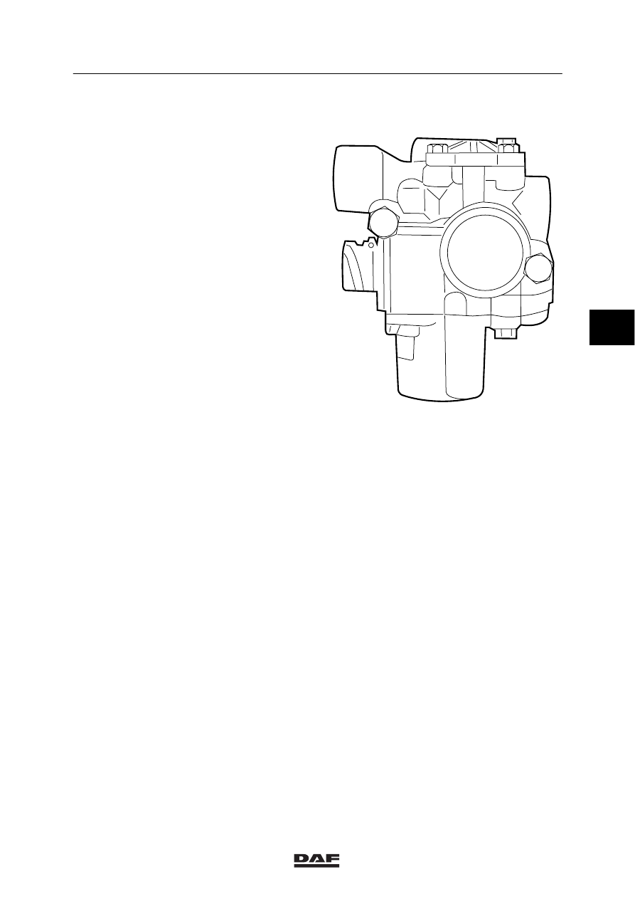
2.11 ABS VALVE
The ABS valve must keep the pressure constant
in the brake chamber during an ABS control, or
decrease the pressure in the brake chamber
regardless of the pressure leaving the foot brake
valve.
If the ABS valve is not operative, it has no
function and the input pressure at connecting
point 1 is the same as the output pressure at
connecting point 2 to the brake chamber.
1
2
R600264
4
ᓻ 200324