DAF CF65, CF75, CF85 Series . Manual - part 896


  Index      DAF     DAF CF65, CF75, CF85 Series - service repair manual


Search            


Content   ..  894  895  896  897   ..


DAF CF65, CF75, CF85 Series . Manual - part 896


6

CF65/75/85 series

Description of components

OPERATION OF BRAKE COMPONENTS

2-19

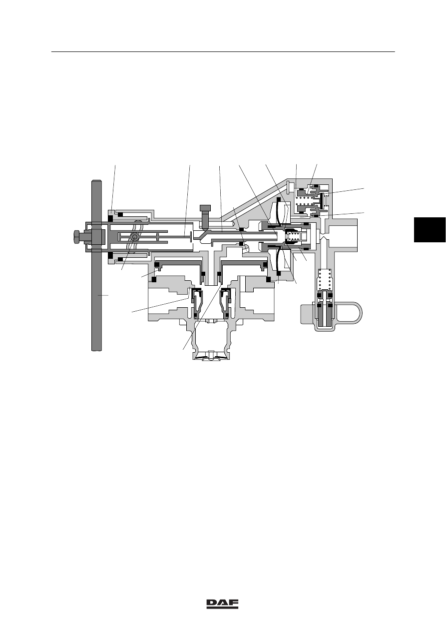
2.10 LOAD SENSING VALVE, LEAF SUSPENSION

Purpose
Automatic control of the brake force depends on
the deflection of the springs and therefore on
the loading condition of the vehicle. Thanks to
the integrated relay valve, the brake cylinders
are aerated and vented quickly.

3

2

1

4

E

C

C

F

D

A

G

B

a

n

o

m

d

g

q

j

i

f

e

l

k

p

h

c b

R600456

Operation
The control valve is attached to the chassis and
connected to the rear axle by means of a rod.
With unloaded vehicles, the distance between
the regulator and the axle is largest and the
lever (j) points fully downwards. When the
vehicle is loaded, this distance decreases and
the lever moves upwards, towards full load
position.
Pin ‘i’ rotates with the lever and moves to the
right via the control groove in bearing cover ‘p’
as a result. Rod ‘q’ brings the tappet (g) in a
position that corresponds with the loading
condition.

4

ᓻ 200324

6

OPERATION OF BRAKE COMPONENTS

Description of components

CF65/75/85 series

2-20

The compressed air provided by the foot brake
valve flows via connection point 4 into chamber
A, pushing piston ‘b’ to the left. Outlet ‘d’ is
closed and inlet ‘m’ is opened, causing
compressed air to enter chamber C to the left of
diaphragm ‘e’. Relay piston ‘f’ is operated via
duct F and chamber G.
At the same time, compressed air flows through
the open valve (a) and duct E into chamber D to
the right of diaphragm ‘e’. Due to this control,
the output pressure at partial load and low
control pressures is increased (to max. 1.4 bar).
If the control pressure increases further, piston
‘n’ is moved to the left against the pressure of
spring ‘o’ and valve ‘a’ closes.

As pressure builds up in chamber G, relay
piston ‘f’ is pressed downwards. Outlet ‘h’ closes
and inlet ‘k’ opens. The air at connection point 1
now flows to the brake cylinders via connection
point 2.

Now pressure will start to build up in chamber B
under relay piston ‘f’. As soon as this pressure
is somewhat higher than that in chamber G, the
piston is pushed upwards and closes inlet ‘k’.

4

ᓻ 200324

6

CF65/75/85 series

Description of components

OPERATION OF BRAKE COMPONENTS

2-21

3

2

1

4

E

C

C

F

D

A

G

B

a

n

o

m

d

g

q

j

i

f

e

l

k

p

h

c b

R600456

When piston ‘b’ is moved to the left, the vanes
(l) attached to it will gradually loosen the
diaphragm (e) from the fixed vanes in the fan
housing. As a result, the effective diaphragm
surface will gradually increase. As soon as the
force of the air to the left of the diaphragm
exceeds that to the right, piston ‘b’ will move to
the right. The inlet (m) will be closed and a set
position is reached.

The position of tappet ‘g’, which is dependent on
the position of lever ‘j’, is indicative of the
effective diaphragm surface and therefore of the
output brake pressure.
The position of tappet ‘g’ determines to what
extent piston ‘b’ must be moved with the vane
disc (l) to allow the valve to build up pressure.
Due to this movement, the effective surface of
the diaphragm will alter.

4

ᓻ 200324

6

OPERATION OF BRAKE COMPONENTS

Description of components

CF65/75/85 series

2-22

In full-load position, this surface and that of
piston ‘b’ are equally large. The control pressure
at connection point 4 is therefore let through
(ratio 1:1) to chambers C and G. The output
pressure at 2 will now equal the control pressure
at connection point 4.

If the pressure at connection point 4 decreases,
the pressure in chamber C will push piston ‘b’ to
the right. Vent ‘d’ will open and the pressure in
chambers C and G will fall. The relay piston will
be pushed up due to the pressure still present in
chamber B causing vent ‘h’ to open. The
pressure at connection point 2 will now fall via
vent 3.

A stop bolt in front of tappet g ensures that this
valve can always provide the minimum brake
pressure if lever ‘j’ is in too low a position due to
a fault. The factory setting of this bolt must not
be changed.

4

ᓻ 200324


Content   ..  894  895  896  897   ..