DAF CF65, CF75, CF85 Series . Manual - part 436


  Index      DAF     DAF CF65, CF75, CF85 Series - service repair manual


Search            


Content   ..  434  435  436  437   ..


DAF CF65, CF75, CF85 Series . Manual - part 436


©

 200416

4-5

Removal and installation

CE ENGINE INLET/EXHAUST SYSTEM

ΧΦ65/75/85 series

4

3

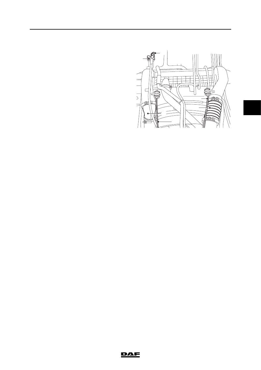
Installing the air cooler
1.

Fit the air cooler and secure it against the 
radiator.

2.

Fit the air-conditioning condenser (if 
applicable) including accessories onto the 
radiator.

3.

Fit the air-conditioning compressor, if 
applicable, to the engine.

4.

Install the torque rods (D).

5.

Fit all rubber hoses that run along the air 
cooler.

6.

Fit the air inlet hoses (C) between the engine 
and the air cooler.

7.

Fit the dipstick holder (B) to the air cooler.

8.

Fit the oil filler pipe (A) to the air cooler.

9.

Top up the cooling system.

i400871

C

D

A

C

B

D

CE ENGINE INLET/EXHAUST SYSTEM

4-6

©

 200416

Removal and installation

3

ΧΦ65/75/85 series

4

4.3 REMOVAL AND INSTALLATION, AIR FILTER ELEMENT

Removing the air filter element
1.

Loosen all the clamping brackets (1) of the 
air filter cover (2).

2.

Remove the air filter cover (2).

3.

Remove the air filter element (3).

4.

Clean the inside of the air filter housing and 
the air filter cover.

5.

When replacing the air filter element, reset 
the air filter indicator, if fitted, by pressing the 
button on the indicator.

i400443

1

5

2

4

3

i400869

©

 200416

4-7

Removal and installation

CE ENGINE INLET/EXHAUST SYSTEM

ΧΦ65/75/85 series

4

3

Installing the air filter element
1.

Fit the air filter element (3) in the air filter 
housing.

2.

Fit the air filter cover. Note the arrow (4) on 
the air filter cover (2).

3.

Fit all the clamping brackets (1).

4.

Check that the flexible sealing bellows (5) on 
the air intake is not damaged. Replace if 
necessary.

i400443

1

5

2

4

3

CE ENGINE INLET/EXHAUST SYSTEM

4-8

©

 200416

Removal and installation

3

ΧΦ65/75/85 series

4

4.4 REMOVAL AND INSTALLATION, GLOW PLUG

Removing the glow plug
1.

Remove the inlet manifold.

2.

Remove the attachment bolts from the glow 
plug and remove the glow plug.

Installing the glow plug
1.

Fit the glow plug and tighten the attachment 
bolts to the specified torque. See "Technical 
data".

2.

Fit the inlet manifold.

M201155


Content   ..  434  435  436  437   ..