DAF CF65, CF75, CF85 Series . Manual - part 435


  Index      DAF     DAF CF65, CF75, CF85 Series - service repair manual


Search            


Content   ..  433  434  435  436   ..


DAF CF65, CF75, CF85 Series . Manual - part 435


©

 200416

4-1

Removal and installation

CE ENGINE INLET/EXHAUST SYSTEM

ΧΦ65/75/85 series

4

3

4. REMOVAL AND INSTALLATION

4.1 REMOVAL AND INSTALLATION, TURBOCHARGER

If the turbocharger to be replaced 
has been damaged to such an extent 
that parts of it are missing or 
lubricating oil has entered the inlet 
system, the inlet and exhaust 
systems must be checked and 
cleaned thoroughly in order to 
prevent serious damage to the 
engine.

Removing the turbocharger
1.

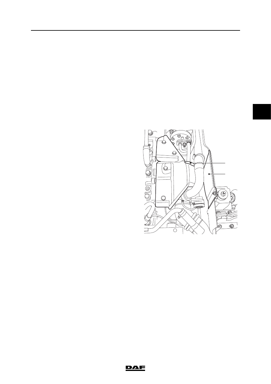
Remove the right-hand engine 
encapsulation (2).

2.

Remove the heat shield (1) from the oil filter.

3.

Remove each charge pipe and the 
turbocharger exhaust pipe.

4.

Remove the oil discharge pipe from the 
turbocharger.

5.

Detach the entire oil supply pipe from the oil 
filter housing to the turbocharger.

6.

Remove the attachment bolts from the 
turbocharger.

7.

Remove the turbocharger.

8.

Immediately plug the openings.

}

1

i400857

2

CE ENGINE INLET/EXHAUST SYSTEM

4-2

©

 200416

Removal and installation

3

ΧΦ65/75/85 series

4

Installing the turbocharger
1.

Clean the turbocharger and the oil supply 
and discharge pipes.

2.

Before installing the turbocharger, check the 
following:
-

the turbocharger housing and connector 
flange for cracks. See "Technical data" 
for rejection standards;

-

the turbocharger shaft must be able to 
rotate freely;

-

the turbocharger shaft must not run out 
of true;

-

the turbocharger pump and turbine 
wheels must not be damaged;

-

there must not be an excessive amount 
of oil in the compressor side of the 
turbocharger. A small amount of oil on 
the inside walls of the compressor side 
is allowed.

3.

Check the adjustment of the turbocharger 
wastegate. See "Inspection and adjustment".

4.

Check the axial bearing play of the 
turbocharger; see "Inspection and 
adjustment".

5.

Check the radial bearing play of the 
turbocharger; see "Inspection and 
adjustment".

6.

Clean the sealing surfaces.

Note:
Always use new gaskets when installing the 
turbocharger.

7.

Apply a layer of Copaslip to the exhaust 
manifold studs.

8.

Fit the turbocharger to the exhaust manifold.

9.

Fit the attachment nuts and tighten them to 
the specified torque. See "Technical data".

©

 200416

4-3

Removal and installation

CE ENGINE INLET/EXHAUST SYSTEM

ΧΦ65/75/85 series

4

3

10. Check that the oil supply and discharge 

pipes are clean and not blocked, kinked or 
cracked. Replace the pipes if necessary.

Note:
If the turbocharger oil supply and/or 
discharge does not function properly, this 
may result in serious damage to the 
turbocharger and/or engine.

11. Fit new O-rings to the oil discharge pipe and 

apply a thin layer of engine oil to them. Fit the 
oil discharge pipe. For the specified 
tightening torque, see "Technical data".

12. Pour clean engine oil into the oil supply of the 

turbocharger and fit the oil supply pipe, after 
fitting a new copper ring, on the oil filter 
housing and the turbocharger. Tighten the 
pipe to the specified tightening torque; see 
"Technical data".

13. Fit the exhaust pipe to the turbocharger.

14. Fit the charge pipes to the exhaust pipe.

15. Fit the heat shield (1) to the oil filter.

16. Install the engine encapsulation (2).

1

i400857

2

CE ENGINE INLET/EXHAUST SYSTEM

4-4

©

 200416

Removal and installation

3

ΧΦ65/75/85 series

4

4.2 REMOVAL AND INSTALLATION OF AIR COOLER

Note:
The removal and installation procedure of the air 
cooler allows for the presence of an air-
conditioning unit.

If such a unit is not present, the sections 
concerned can be skipped.

Removing the air cooler
1.

Partially drain the coolant.

2.

Disconnect the oil filler pipe (A) from the air 
cooler.

3.

Disconnect the dipstick holder (B) from the 
air cooler.

4.

Remove the air inlet hoses (C) between the 
engine and the air cooler.

5.

Disconnect all rubber hoses that run along 
the air cooler.

6.

Disconnect the torque rods (D) at the side of 
the air cooler.

7.

Disconnect the air-conditioning condenser (if 
applicable) including accessories from the 
radiator.

8.

Disconnect the air-conditioning compressor, 
if applicable, from the engine and carefully 
put the complete air-conditioning system to 
one side.

9.

Disconnect the air cooler from the radiator 
and remove the air cooler.

i400871

C

D

A

C

B

D


Content   ..  433  434  435  436   ..