DAF CF65, CF75, CF85 Series . Manual - part 434
©
200416
3-5
Inspection and adjustment
CE ENGINE INLET/EXHAUST SYSTEM
ΧΦ65/75/85 series
4
3
3.5 INSPECTION AND PRESSURE-TESTING, AIR INLET SYSTEM
When pressure-testing the air inlet
system, the plugs may spring off if
they are not properly secured. It is
therefore important to check the
attachment of the plugs before
pressure-testing and keep people
away from the area.
1.
Check the condition and mounting of the air
inlet channels/pipes of the air inlet system.
Note:
In case of doubt as to the proper sealing of
the air inlet system, which is indicated by the
following:
- loss of power
- high fuel consumption
- unusual noises
- lit engine fault symbol on the instrument
panel, ???carry out a pressure test to check
the air inlet system for leakage.
2.
Remove the right-hand and rear engine
encapsulations.
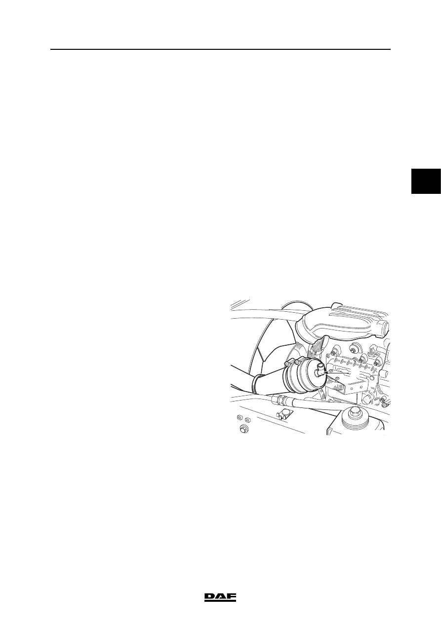
3.
Loosen the inlet hose between the air cooler
and the inlet manifold at the inlet manifold
side.
4.
Fit the special tool (DAF no. 1453171) in the
hose.
}
A
i400856