DAF CF65, CF75, CF85 Series . Manual - part 394


  Index      DAF     DAF CF65, CF75, CF85 Series - service repair manual


Search            


Content   ..  392  393  394  395   ..


DAF CF65, CF75, CF85 Series . Manual - part 394


3

CF65/75/85 series

Description of components

AS TRONIC GEARBOX

2-3

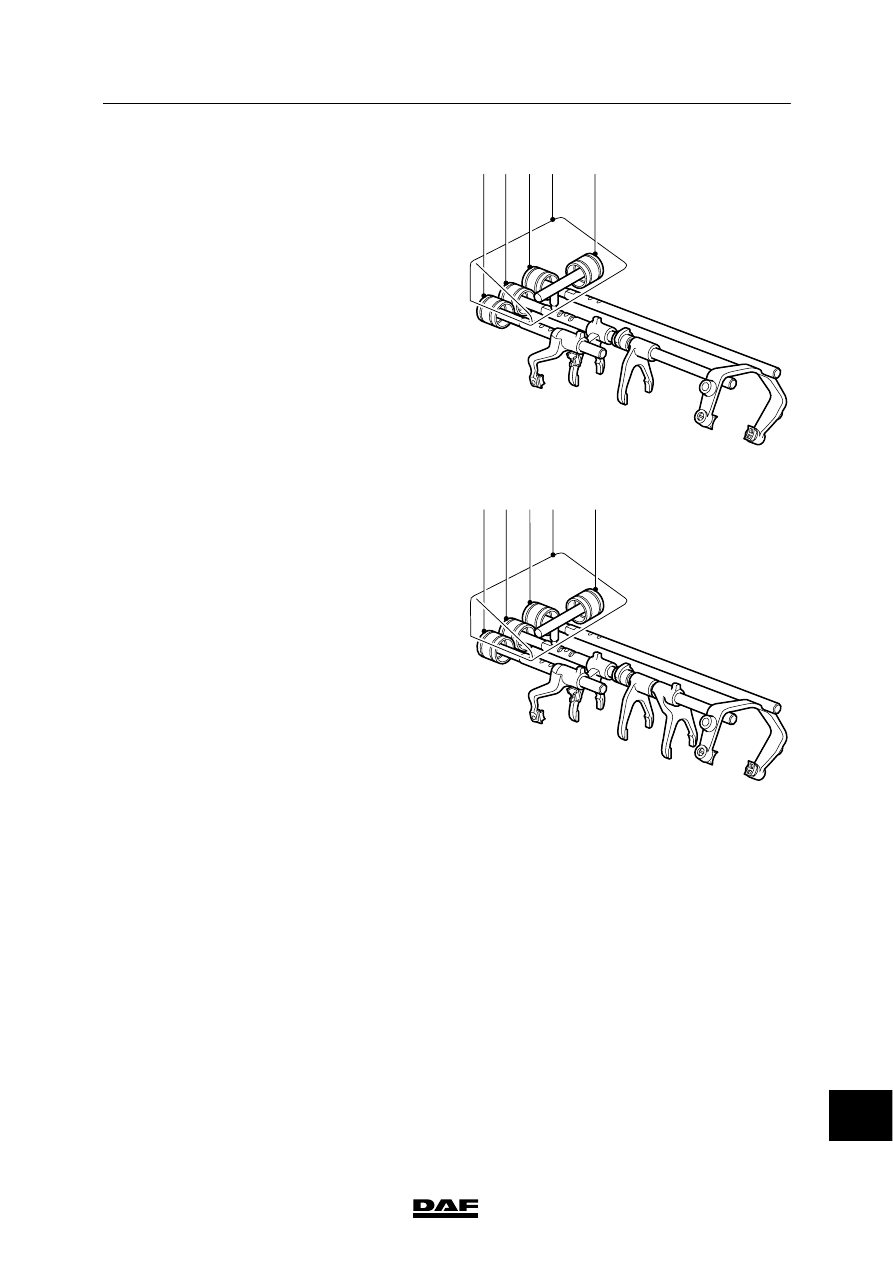
The figures alongside show the situations with a
12AS or 16AS gearbox.

V300659

12 AS

3

2

5

1

4

GV

GP

2/3

1/R

V300658

16 AS

3

2

5

1

4

GV

GP

3/4

2/1

R

14

ᓻ 200337

3

AS TRONIC GEARBOX

Description of components

CF65/75/85 series

2-4

2.2 OPERATING UNIT

The operating unit (2) is not mechanically
connected to the gearbox. Operation is effected
via the selector switch (3) and the gear lever (1).

The operating unit contains various
position sensors that register the position of the
gear lever.
In this way the information relating to the correct
gear is transmitted to the gearbox modulator via
the internal electronics of the operating unit and
the cab wiring.

3

2

1

V300726

2.3 TRANSMISSION BRAKE

V300708

1

4

3

6

7

8

9

10

5

2

The transmission brake is located in the front
gearbox cover (2), which is situated in the clutch
housing. The transmission brake consists of a
piston (4), multiple lamella clutch (5, 6) and the
clutch cover (7).

14

ᓻ 200337

3

CF65/75/85 series

Description of components

AS TRONIC GEARBOX

2-5

The transmission brake is operated
pneumatically by the piston (4). During changing
up the speeds of the secondary shafts, and
therefore the speeds of the main-box gear
wheels too, must be braked in respect of the
main shaft.
This is necessary so as to engage a subsequent
gear and because the main box has not been
synchronised.

The transmission brake is actuated by a
solenoid valve in the gearbox modulator. This
valve actuates the piston (4) pneumatically via
an air duct in the gearbox housing and the air
duct (1) in the cover.

The adjustable air pressure will cause the
piston (4) to move the lamellae (5, 6) against the
clutch cover (7). The clutch cover (7) and the
pressure plates (5) are locked in position relative
to the gearbox housing by means of recesses
and pins (12).

In this way the auxiliary shaft (13) can be
braked, so that gears can be shifted.

After a change of gear, the clutch of the
transmission brake is no longer operated. The
spring (10) and hollow pin (9) in the auxiliary
shaft (13) force the piston back, so that the
clutch is released.

A metal hit pin (11) serves to reduce wear of the
lightweight-metal piston (4).

10

8

7

12

5

6

13

1

3
4

11

9

V300709

2

14

ᓻ 200337

3

AS TRONIC GEARBOX

Description of components

CF65/75/85 series

2-6

14

ᓻ 200337


Content   ..  392  393  394  395   ..