DAF CF65, CF75, CF85 Series . Manual - part 393


  Index      DAF     DAF CF65, CF75, CF85 Series - service repair manual


Search            


Content   ..  391  392  393  394   ..


DAF CF65, CF75, CF85 Series . Manual - part 393


3

CF65/75/85 series

General

AS TRONIC GEARBOX

1-5

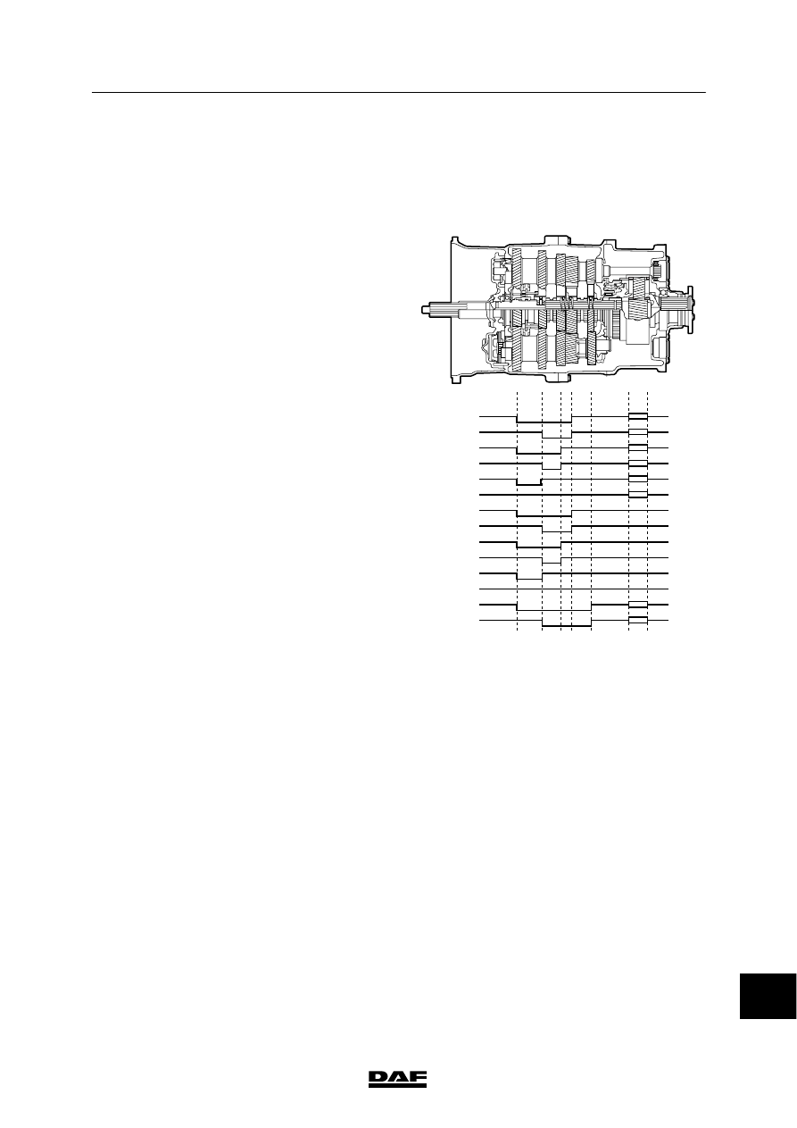
In popular terms, the number of gears in the
main box is “stacked”. This is why the term
“stacking box” or range box was created.

The diagrams show the power distribution
across the individual gear pairs for each gear.

AS Tronic 12 gears
By means of the splitter range, the three gears
in the main box are multiplied by two,
while using the rear-mounted range box
multiplies this figure by two again. This results
in 2x3x2 = 12 forward gears.

V300663

1

2

3

4

5

6

7

8

9

10

11

12

R1

R2

ᓻ 200337

14

3

AS TRONIC GEARBOX

General

CF65/75/85 series

1-6

AS Tronic 16 gears
By means of the splitter range, the four gears in
the main box are multiplied by two, while
using the rear-mounted range box multiplies this
figure by two again. This results in 2x4x2 = 16
forward gears.

V300664

1

2

3

4

5

6

7

8

9

10

11

12

13

14

15

16

R1

R2

ᓻ 200337

14

3

CF65/75/85 series

Description of components

AS TRONIC GEARBOX

2-1

2. DESCRIPTION OF COMPONENTS

2.1 GEARBOX MODULATOR

The gearbox modulator (2) is integrated in the
gearbox housing (1) (to save space) and has all
mechanical, electrical and pneumatic
connections that are necessary for correct
shifting of the gearbox.

V300698

2

1

14

ᓻ 200337

3

AS TRONIC GEARBOX

Description of components

CF65/75/85 series

2-2

The gearbox modulator is to ensure that the
gearbox shifts fast and correctly, depending on
the current driving conditions.
All functions that are necessary for selection and
checking of the correct gear are controlled
inside the gearbox modulator.

The gearbox modulator contains the following
components:
-

The control unit (ECU)

-

Pneumatic solenoid valves and engaging
cylinders

-

Travel sensors to determine the current
position of all engaging cylinders

-

Sensors for checking the gearbox and
modulator temperatures, rpm of input shaft
and pressure sensor for the air supply to the
pneumatic system

The integrated gearbox electronics are situated
in the upper modulator cover. The electronics
serve to actuate and control the entire
automated gear selector system (gearbox,
clutch, PTO), depending on the driving
conditions (correct gear, fully automatic mode,
operating condition of the vehicle).

Electropneumatic actuation of the gearbox
control is effected by 10 individual pneumatic
solenoid valves.
One solenoid valve functions as the main cut-off
valve for the air supply. A combination of 8
solenoid valves ensures that the engaging
cylinders (1, 2, 4 and 5) are actuated. One
solenoid valve actuates the transmission brake
via an air duct in the gearbox housing.

Engaging cylinder 1 engages the main box and
the selector cylinder (2) ensures that the right
gate is selected for the main box.
The splitter range (GV) is operated by engaging
cylinder 4. The rear-mounted range box (GP) is
operated by engaging cylinder 5.

14

ᓻ 200337


Content   ..  391  392  393  394   ..