DAF CF65, CF75, CF85 Series . Manual - part 353
3
CF65/75/85 series
Description of components
CLUTCH
3-9
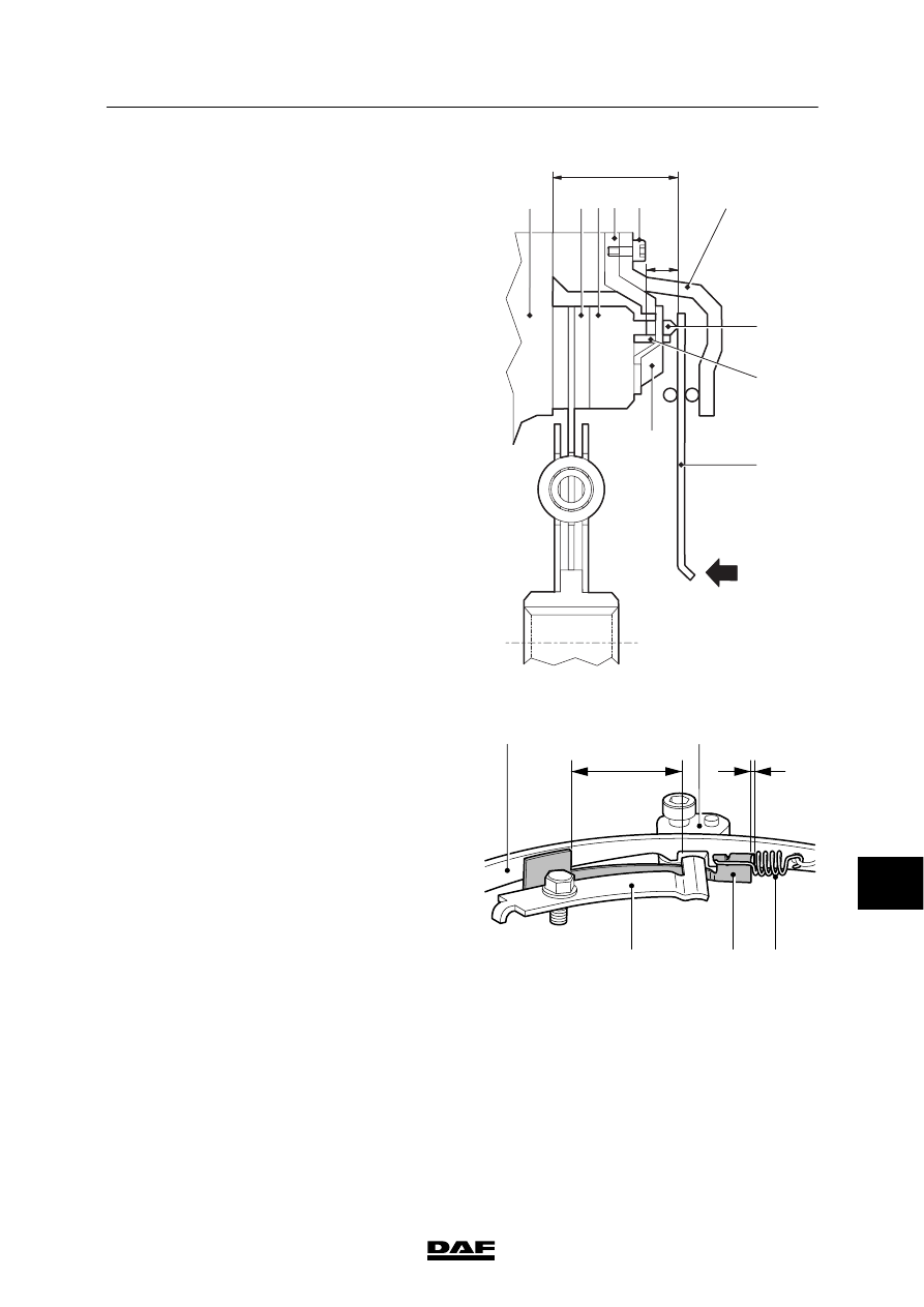
A push-type clutch with an automatically
adjusting clutch release assembly is described
here as an example.
As the result of wear, the lining of the clutch
plate becomes thinner and the distance (A)
between the flywheel and the diaphragm spring
decreases. However, distance A is kept constant
by the automatically adjusting clutch release
assembly. The adjustment (compensation) takes
place as the clutch is operated by temporarily
relieving the contact pressure of the diaphragm
spring.
7
6
1 2
3
A
C
11
12
4
V300484
8
5
Compensation of rest position of diaphragm
spring
The adjustment takes place as follows: as the
clutch plate (12) wears, the thrust plate (1)
moves towards the flywheel (11). This causes
the stop plate (2) to bend the stop spring (5),
which is fastened to the thrust plate (1), upwards
proportionately. The stop plate (2) is fastened to
the clutch release assembly cover (4).
The pre-adjusting spring (9) will now pull the
slide plate (7) against the adjusting ring (6). This
eliminates the gap (B) in the recess of the
adjusting ring (6). The rising end of the slide
plate (7) also locks under the stop spring (5).
V300485
6
B
D
2
9
7
5
10
ᓻ 200337