DAF CF65, CF75, CF85 Series . Manual - part 351


  Index      DAF     DAF CF65, CF75, CF85 Series - service repair manual


Search            


Content   ..  349  350  351  352   ..


DAF CF65, CF75, CF85 Series . Manual - part 351


3

CF65/75/85 series

Description of components

CLUTCH

3-1

3. DESCRIPTION OF COMPONENTS
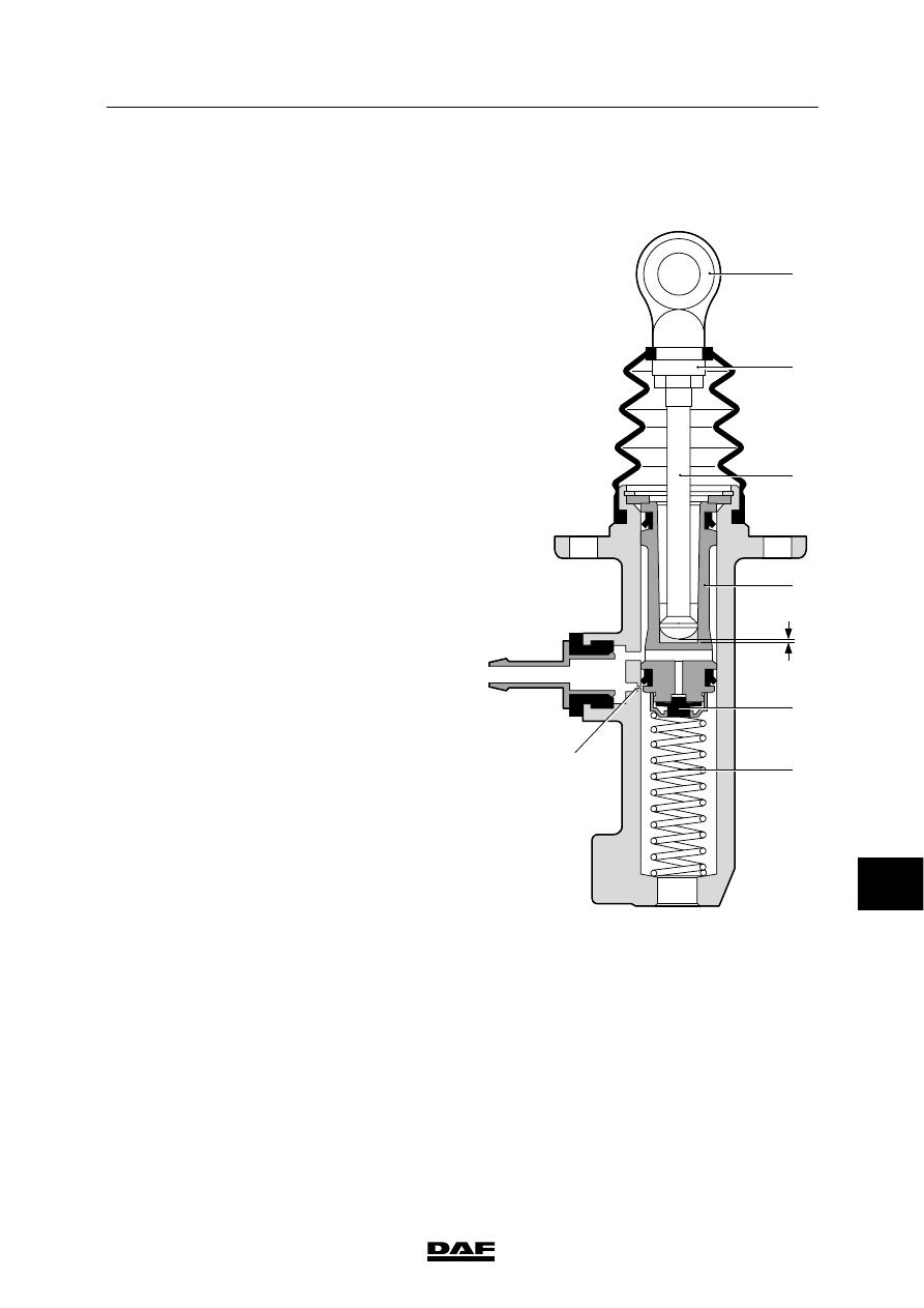
3.1 MAIN CYLINDER

When the clutch pedal is depressed, the thrust
pin (3) will move the piston (4) down against the
spring (6).
As a result, the valve (5) closes and the
pressure starts to build up as the sleeve passes
the bore hole (7) to the reservoir.

When the clutch pedal is released, the spring (6)
ensures that the piston (4) returns to the original
position.
Any shortage of fluid underneath the piston (4)
is refilled via a bore hole in the piston (6) and
the valve (5).
It is important that after depressing the clutch
pedal, the piston (4) returns fully to the original
position, so that the 0. 6 mm compensation hole
(7) is not closed by the seal on the piston (4).
If the compensation hole is not entirely free,
residual pressure will build up, causing
excessive damage to the clutch mechanism.
The piston (4) can return fully to the original
position if there is sufficient play (E) between the
thrust pin (3) and the piston (4). See “Technical
data”.

V300411

1

E

2

3

4

5

6

7

10

ᓻ 200337

3

CLUTCH

Description of components

CF65/75/85 series

3-2

3.2 CF75/85 CLUTCH SERVO

A

A

8

3 2

7

1

6

10

5

11

4

9

V300412

Cross-section A - A

Declutching
Depressing the clutch pedal results in a build-up
of hydraulic pressure.

This causes the servo piston (1) to push the air
valve (2) from the valve seat, against the force
of the spring (3).

Air pressure now flows into the cylinder.

10

ᓻ 200337

3

CF65/75/85 series

Description of components

CLUTCH

3-3

The pressure pin (4) is pushed forward by the
air pressure building up on the air piston (5) and
the hydraulic pressure on the fluid piston (6).

The pressure pin (4) pushes against the clutch
lever, which results in declutching.

State of equilibrium
When the hydraulic pressure and pneumatic
support push the pressure pin (4) forwards, a
state of equilibrium is achieved between the air
pressure and hydraulic pressure (status when
the clutch pedal is not depressed any further).

The servo piston (1) again seals off against the
valve seat, closing the air supply and stopping
the build-up of pneumatic pressure.

Clutching
When the clutch pedal is released, there is no
longer any hydraulic pressure and the servo
piston (1) will be pushed back into its original
position by the pressure spring (7) and any
remaining pneumatic support.

As a result, the bleed bore (8) in the servo
piston (1) is no longer closed, and bleeding
takes place via the bleed vent (9).

Vent opening
The function of the vent opening (10) is to
prevent a build-up of pressure between both
piston seals.

10

ᓻ 200337

3

CLUTCH

Description of components

CF65/75/85 series

3-4

3.3 CF65 CLUTCH SERVO

3

2

7

1

10

8
9

 A-A

4

5

6

A

V300352

A

Cross-section A - A

Declutching
Depressing the clutch pedal results in a build-up
of hydraulic pressure.

10

ᓻ 200337


Content   ..  349  350  351  352   ..