DAF CF65, CF75, CF85 Series . Manual - part 315


  Index      DAF     DAF CF65, CF75, CF85 Series - service repair manual


Search            


Content   ..  313  314  315  316   ..


DAF CF65, CF75, CF85 Series . Manual - part 315


3

CF65/75/85 series

Inspection and adjustment

GEARBOX - PNEUMATIC SECTION

3-1

3. INSPECTION AND ADJUSTMENT

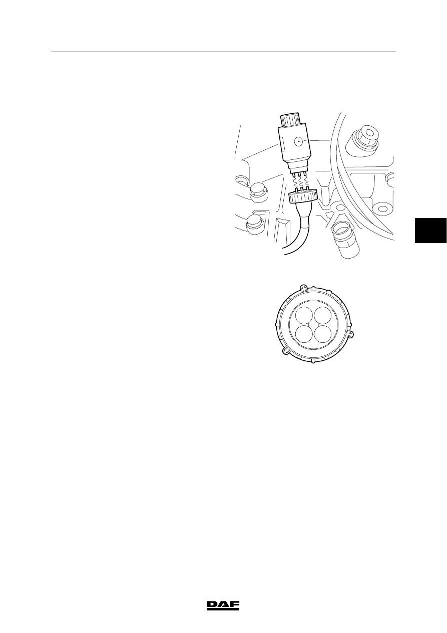
3.1 SIMULATION OF THE SPEED SIGNAL

The speed signal can be simulated using DELSI
(DAF No. 0694941). DELSI must be connected
to the speed sensor connector.

To connect DELSI to the speed sensor
connector, an adapter cable needs to be made.
The adapter cable must consist of the following
wiring:

Pin 1:

speed sensor, power supply

Pin 2:

speed sensor, earth

Pin 3:

speed sensor,
real-time speed/distance signal

Pin 4:

not in use

When the speed sensor connector is
disconnected, a fault is stored in the tachograph.
This error can be deleted using DAVIE XD.

V300425

2

4

3

1

K100873

4

ᓻ 200337

3

GEARBOX - PNEUMATIC SECTION

Inspection and adjustment

CF65/75/85 series

3-2

3.2 INSPECTION, DOWNSHIFT PROTECTION VALVE

Inspection without vehicle speed signal
1.

Ensure there is sufficient air pressure.

2.

Position the gear lever in neutral.

3.

Switch the vehicle ignition on.

4.

Use the range-change switch (B) on the
gear lever to select the lower range. The
range-change gear should now switch to
the lower range.

5.

Switch off the vehicle ignition. The
range-change gear should now
automatically switch to the higher range.

B

A

D000096

Inspection with the vehicle speed signal
1.

Ensure there is sufficient air pressure.

2.

Connect special tool Delsi-2
(DAF No. 0694941).

V300425

4

ᓻ 200337

3

CF65/75/85 series

Inspection and adjustment

GEARBOX - PNEUMATIC SECTION

3-3

3.

Position the gear lever in neutral.

4.

Switch the vehicle ignition on.

5.

Use the range-change switch (B) on the
gear lever to select the lower range. The
range-change gear should now switch to
the lower range.

B

A

D000096

6.

Use Delsi-2 to raise the simulated vehicle
speed slowly to approximately 40 km/h. As
the vehicle speed increases, the
range-change gear should automatically
switch to the higher range.

7.

Use Delsi-2 to lower the simulated vehicle
speed slowly to approximately 0 km/h. As
the vehicle speed drops, the range-change
gear should automatically switch to the
lower range.

V300426

4

ᓻ 200337

3

GEARBOX - PNEUMATIC SECTION

Inspection and adjustment

CF65/75/85 series

3-4

3.3 INSPECTION AND ADJUSTMENT, ZF/EATON GEARBOX GV VALVE

Inspection, ZF gearbox GV valve
1.

Ensure that the gearbox is in neutral and
the parking brake is engaged.

2.

Start the engine and run it at idling speed.

3.

Use the rocker switch (A ) on the gear lever
to select the other splitter mode without
depressing the clutch pedal.

4.

Carefully push the gear lever in the direction
of reverse, until the teeth in the gearbox
start to rattle.

5.

Slowly depress the clutch pedal until the
gear can be engaged in regular fashion
(without rattling).

Note:
After the gear has been engaged or the
rattling has stopped, the splitter must switch
to the pre-selected mode (high or low,
depending on the pre-selected position).

Inspection, Eaton gearbox GV valve
1.

Ensure that the gearbox is in neutral and
the parking brake is engaged.

2.

Start the engine and run it at idling speed.

3.

Carefully push the gear lever in the direction
of reverse, until the teeth in the gearbox
start to rattle.

4.

Slowly depress the clutch pedal until the
gear can be engaged in regular fashion
(without rattling). This point must be the
same as distance C. See “Technical data”.

B

A

D000096

V300315

C

D

B

1

A

4

ᓻ 200337


Content   ..  313  314  315  316   ..