DAF CF65, CF75, CF85 Series . Manual - part 140


  Index      DAF     DAF CF65, CF75, CF85 Series - service repair manual


Search            


Content   ..  138  139  140  141   ..


DAF CF65, CF75, CF85 Series . Manual - part 140


©

 200346

4-21

Removal and installation

CAB SUSPENSION

ΧΦ65/75/85 series

1

5

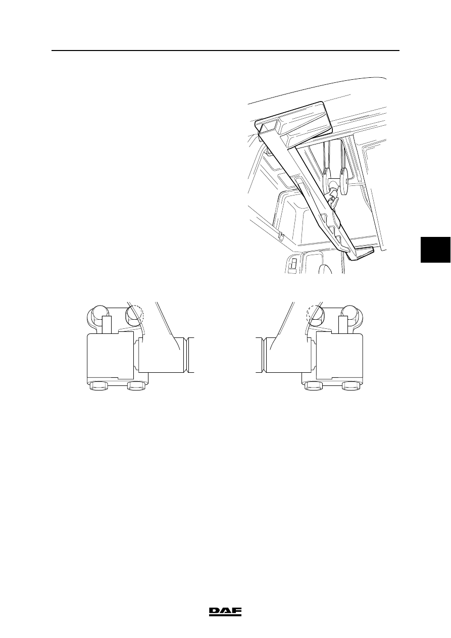
36. Lower the hoist through the roof hatch and fit 

the lifting yoke.

37. With the cab tilting mechanism in the lifting 

position, make a number of pump strokes 
until both cab locks are disengaged.

38. Slacken the attachment bolts for the cab 

suspension.

39. On both sides remove the foremost bolts (3 

and 4) from the stabiliser bearing bracket 
and remove the bolts (2) at the rear.

40. Hoist the cab carefully a little way so that the 

bolts can be removed from the cab 
suspension.

41. Remove the attachment bolt that attaches 

the lifting cylinder to the cab.

42. Hoist the cab carefully a little way and check 

that all pipes and wiring harnesses are 
disconnected.

43. Carefully lift the cab from the vehicle. Place 

the cab on a cab support or another suitable 
frame.

K1 01 076

2

3

4

1

1

4

3

2

K1 01 648

CAB SUSPENSION

4-22

©

 200346

Removal and installation

5

ΧΦ65/75/85 series

1

Installing complete cab

}

When working on the cab 
suspension provide extra supports 
for the cab to avoid the risk of being 
trapped.

1.

Fit the hoist yoke.

2.

Before placing the cab on the chassis 
supports check to see if the wiring holes in 
the aluminium chassis are accessible. This 
makes the work easier.

3.

Check that the contact surfaces of the 
stabiliser bearing brackets and the chassis 
supports are clean.

4.

Check that the gear lever is in 2

nd

 or 4

th

 gear.

5.

Place the cab above the chassis and lower it 
carefully onto the chassis supports. Check 
that the wiring harnesses and any piping do 
not get trapped.

6.

Position the stabiliser bearing brackets in 
relation to the chassis supports.

7.

Fit the attachment bolts (2), (3) and (4) on the 
right-hand side of the vehicle. Tighten the 
bolts but not yet to the specified torque.

8.

Tighten the attachment bolts (3) and (4) to 
the specified torque. See "Technical data".

9.

Fit the attachment bolts (2), (3) and (4) on the 
left-hand side of the vehicle but do not yet 
tighten these bolts to the specified torque. 
The stabiliser bearing bracket must still be 
able to move.

10. Position the lift cylinder and fit the bolt. 

Tighten the bolt to the specified torque. See 
"Technical data".

Note:
Before fitting the prestressed bolt check that 
the threaded hole in the aluminium chassis 
bracket has a screw thread.

K1 01 076

2

3

4

1

K1 01 021

1

4

3

2

K1 01 022

©

 200346

4-23

Removal and installation

CAB SUSPENSION

ΧΦ65/75/85 series

1

5

11. Fit the prestressed bolt (1). Tighten the 

prestressed bolt to the specified torque. See 
"Technical data".

12. Lower the cab and remove the hoist yoke.

13. Check whether the gear lever is in neutral.

14. Tilt the cab completely forward.

15. Insert the bolt (1) on the right-hand side of 

the vehicle and tighten both bolts (1) and (2) 
on the rear to the specified torque. See 
"Technical data".

16. On the left side place the bolt (1). Fit the bolts 

(1), (2), (3) and (4) of the stabiliser bearing 
support in the specified order and to the 
specified torque. See "Technical data".

17. Remove the prestressed bolt.

18. Attach the bracket for the height control 

valve.

K1 01 066

1

2

3

4

1

K1 01 021

1

4

3

2

K1 00 941

CAB SUSPENSION

4-24

©

 200346

Removal and installation

5

ΧΦ65/75/85 series

1

19. Put the coupling block with air pipes in place 

and secure it using the attachment bolts (2).

20. Connect the connector (1) of the lighting on 

the left side. Fasten the wiring harness with 
ties.

21. Fit the steering-column shaft to the steering-

box input shaft. The groove (A) in the 
coupling must be aligned with the mark (B) 
on the input shaft of the steering box.

}

Check that the steering shaft is 
correctly in place on the input shaft 
so that the attachment bolt can be 
put in the notch (C).

22. Only fit a new attachment bolt and 

attachment nut to the universal joint. Tighten 
the attachment bolt to the specified torque. 
See "Technical data".

23. Attach the pipe for the clutch cylinder (on 

chassis side member). Fasten the pipe with 
the special clips for that purpose.

24. Attach the heater hoses (1) to the underside 

of the cab and attach the heater hose to the 
front of the cab.

K1 01 036

1

2

K1 01 353

A

K1 01 067

1


Content   ..  138  139  140  141   ..