DAF CF65, CF75, CF85 Series . Manual - part 141


  Index      DAF     DAF CF65, CF75, CF85 Series - service repair manual


Search            


Content   ..  139  140  141  142   ..


DAF CF65, CF75, CF85 Series . Manual - part 141


©

 200346

4-25

Removal and installation

CAB SUSPENSION

ΧΦ65/75/85 series

1

5

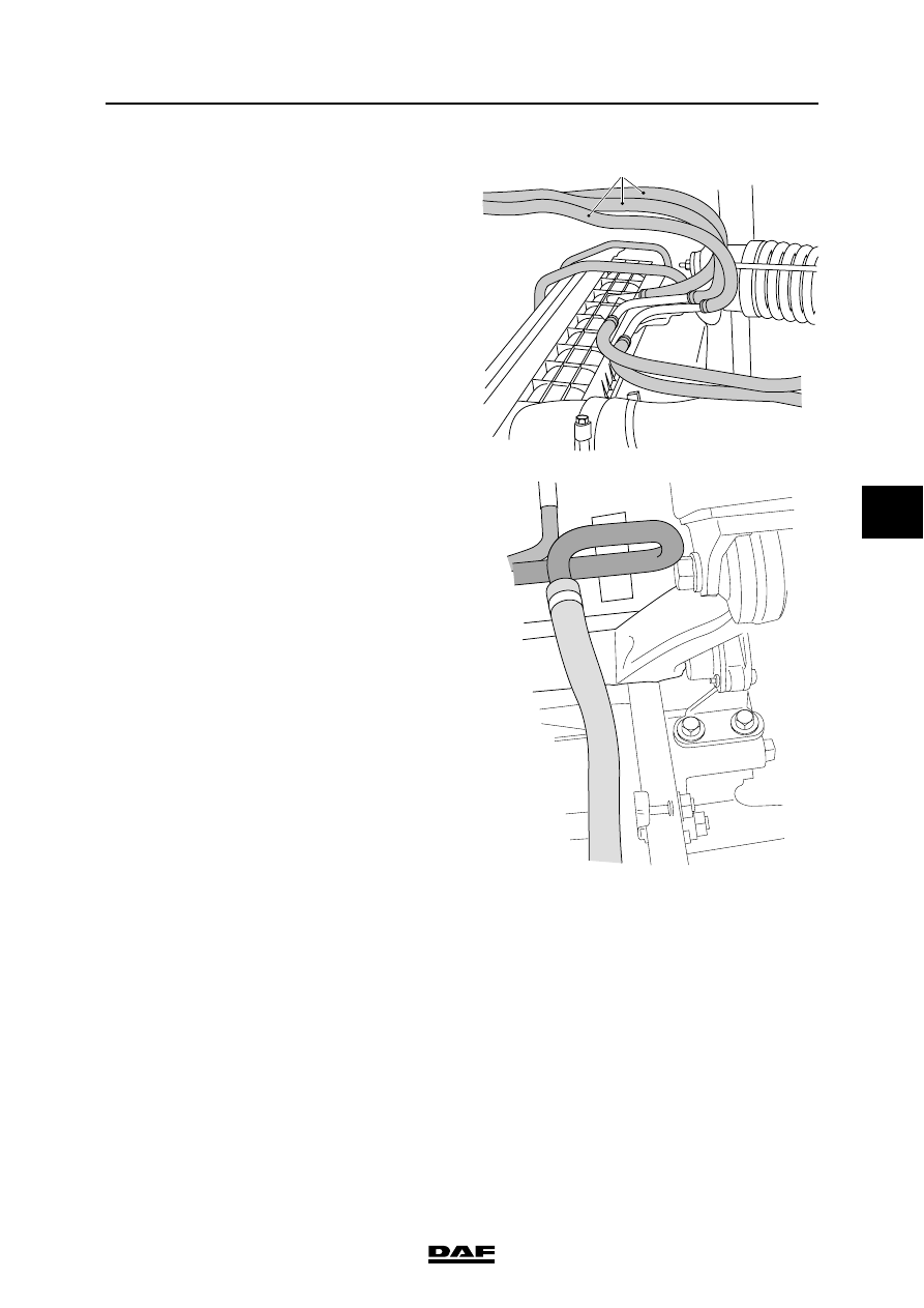
25. Attach the coolant hoses (1) from the engine 

to the expansion reservoir.

26. Attach the coolant hose from the expansion 

reservoir to the engine.

K1 01 037

1

K1 01 039

CAB SUSPENSION

4-26

©

 200346

Removal and installation

5

ΧΦ65/75/85 series

1

27. Connect the connector (1) of the lighting on 

the right-hand side.

28. Install the connector (2) on the air supply 

unit.

29. If present, attach the fuel pipe to the cab 

heater.

30. Connect the pipe to the clutch cylinder. Fix 

the pipe securely with a clamp to prevent the 
pipe from chafing.

31. Install the air conditioning pipes and secure 

them using the attachment nuts.

32. Fit the lower cover of the cab lead through.

33. Fit the connectors and the cables in the cab 

lead through. Seal the tachograph.

34. Fit the cover of the cab lead through.

35. Fit the vehicle grille.

36. Fit the corner pieces.

37. Bleed the clutch cylinder.

38. Connect the air pipe to the splitter control 

valve.

39. Fill the cooling system.

40. Fit the earth lead to the battery terminal.

41. Let the engine idle and top up the cooling 

system, if necessary.

42. If applicable, fill the air conditioning system.

K1 01 032

1

2

K1 01 035

©

 200346

1

Contents

CAB TILTING MECHANISM

ΧΦ65/75/85 series

1

6

6 Cab tilting mechan ism

CONTENTS

Page

Date

1.

SAFETY INSTRUCTIONS. . . . . . . . . . . . . . . . . . . . . . . . . . . . . . . . . . . . . . . . . . 1-1 . . . . . 200346
1.1

Safety instructions . . . . . . . . . . . . . . . . . . . . . . . . . . . . . . . . . . . . . . . . . . . 1-1 . . . . . 200346

2.

GENERAL . . . . . . . . . . . . . . . . . . . . . . . . . . . . . . . . . . . . . . . . . . . . . . . . . . . . . . 2-1 . . . . . 200346
2.1

Operation, tilting mechanism . . . . . . . . . . . . . . . . . . . . . . . . . . . . . . . . . . . 2-1 . . . . . 200346

2.2

Overview drawing, cab tilting pump . . . . . . . . . . . . . . . . . . . . . . . . . . . . . . 2-4 . . . . . 200346

2.3

Overview drawing, lifting cylinder  . . . . . . . . . . . . . . . . . . . . . . . . . . . . . . . 2-5 . . . . . 200346

3.

INSPECTION AND ADJUSTMENT. . . . . . . . . . . . . . . . . . . . . . . . . . . . . . . . . . . 3-1 . . . . . 200346
3.1

Inspecting tilting mechanism . . . . . . . . . . . . . . . . . . . . . . . . . . . . . . . . . . . 3-1 . . . . . 200346

3.2

Inspection and adjustment, pressure limiting valve of cab tilting pump . . . 3-2 . . . . . 200346

4.

REMOVAL AND INSTALLATION. . . . . . . . . . . . . . . . . . . . . . . . . . . . . . . . . . . . 4-1 . . . . . 200346
4.1

Removal and installation, cab tilting pump  . . . . . . . . . . . . . . . . . . . . . . . . 4-1 . . . . . 200346

4.2

Removal and installation, lifting cylinder . . . . . . . . . . . . . . . . . . . . . . . . . . 4-2 . . . . . 200346

4.3

Removal and installation, cab tilting pump seals . . . . . . . . . . . . . . . . . . . . 4-6 . . . . . 200346

4.4

Removal and installation, cab tilting pump two-way valve. . . . . . . . . . . . . 4-9 . . . . . 200346

5.

DISASSEMBLY AND ASSEMBLY . . . . . . . . . . . . . . . . . . . . . . . . . . . . . . . . . . . 5-1 . . . . . 200346
5.1

Disassembly and assembly, lifting cylinder . . . . . . . . . . . . . . . . . . . . . . . . 5-1 . . . . . 200346

6.

DRAINING AND FILLING . . . . . . . . . . . . . . . . . . . . . . . . . . . . . . . . . . . . . . . . . . 6-1 . . . . . 200346
6.1

Filling and bleeding, tilting mechanism  . . . . . . . . . . . . . . . . . . . . . . . . . . . 6-1 . . . . . 200346

CAB TILTING MECHANISM

2

©

 200346

Contents

6

ΧΦ65/75/85 series

1


Content   ..  139  140  141  142   ..