DAF CF65, CF75, CF85 Series . Manual - part 139


  Index      DAF     DAF CF65, CF75, CF85 Series - service repair manual


Search            


Content   ..  137  138  139  140   ..


DAF CF65, CF75, CF85 Series . Manual - part 139


©

 200346

4-17

Removal and installation

CAB SUSPENSION

ΧΦ65/75/85 series

1

5

4.10 REMOVAL AND INSTALLATION, COMPLETE CAB

}

Only use approved lifting 
equipment. Comply with general 
safety instructions when working 
with lifting equipment.

Removing complete cab
1.

Remove the battery earth cables.

2.

Put the gear lever in 2

nd

 or 4

th

 gear. Put the 

wheels in the straight-line position.

3.

Open the cab grille.

Note:
Work on the air conditioning unit should only 
be carried out by qualified personnel.

4.

If present, drain the air conditioning unit.

5.

Drain the clutch fluid.

6.

Drain the coolant.

7.

Remove the covers from around the 
headlights.

8.

Remove the vehicle grille.

9.

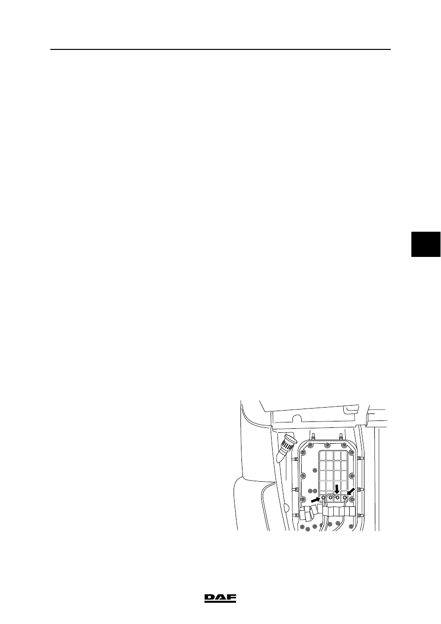
Remove the cover from the cab lead 
through.

10. Check that the wiring harnesses are marked. 

If not, mark them.

11. Detach the connectors in the cab lead 

through.

12. Remove the cover at the bottom of the cab 

lead through.

13. Disconnect the wiring harnesses.

14. Detach the positive and the earth leads in the 

cab lead through.

15. Remove the air pipe from the splitter control 

valve.

16. Remove the hose from the main clutch 

cylinder.

17. Tilt the cab.

18. Loosen the wiring harnesses from the cab 

lead through as much as is necessary.

K1 01 035

CAB SUSPENSION

4-18

©

 200346

Removal and installation

5

ΧΦ65/75/85 series

1

19. Loosen the wiring harness (1) from the 

lighting unit as much as is necessary.

20. Disconnect the connector (2) from the air 

supply unit. Loosen the wiring harness as 
much as is necessary.

21. If present, release the fuel pipe from the cab 

heater at the rubber joint.

22. On the steering box side loosen the wiring 

harness that goes to the lighting unit (1) as 
much as is necessary. Loosen the 
connector.

23. Take the pressure off the air system.

24. Remove the attachment bolts (2) from the air 

duct block and put the loose half to one side.

25. Loosen one of the universal joints of the 

steering shaft (which one depends on the 
operation to be performed; either the 
universal joint beneath the steering wheel or 
the universal joint on the steering box). 
Before loosening, mark the position of the 
universal joint in relation to the steering 
shaft.

26. Remove the clamp bolt from the universal 

joint.

27. Remove the universal joint from the steering 

box input shaft.

K1 01 032

1

2

K1 01 036

1

2

©

 200346

4-19

Removal and installation

CAB SUSPENSION

ΧΦ65/75/85 series

1

5

28. Disconnect the three bleed hoses (1) that are 

connected to the expansion reservoir.

29. Remove the heater hoses (1) on the steering 

box side.

K1 01 037

1

K1 01 067

1

CAB SUSPENSION

4-20

©

 200346

Removal and installation

5

ΧΦ65/75/85 series

1

30. Remove the heater hose on the side of the 

air supply unit.

31. Slacken the attachment bolt that holds the 

lifting cylinder to the cab by one turn.

32. On both sides remove the rearmost bolts (1) 

from the stabiliser bearing bracket and 
slacken the bolts (2) on both sides by one 
turn

33. Tilt the cab back.

34. Remove the glass from the roof hatch.

35. Open both doors and secure them.

K1 01 039

2

3

4

1

1

4

3

2

K1 01 648


Content   ..  137  138  139  140   ..