DAF CF65, CF75, CF85 Series . Manual - part 110
©
200346
4-39
Removal and installation
INTERNAL CAB COMPONENTS
ΧΦ65/75/85 series
1
2
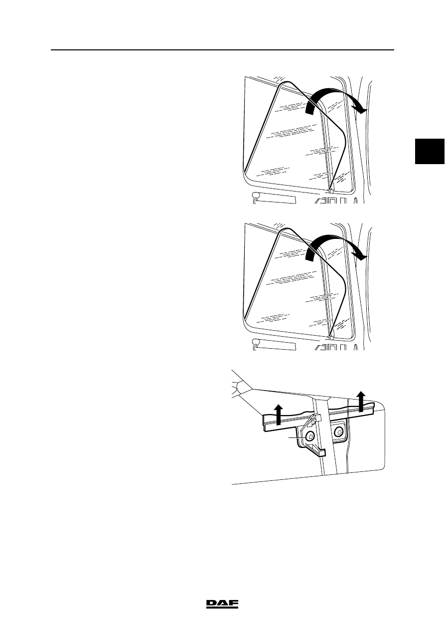
5.
Raise the glass, tilt the window inwards and
remove it from the door.
Installing drop glass
1.
Position the drop glass in the door.
2.
Secure the drop glass to the window
mechanism, using the attachment bolts (2).
K1 00 612
K1 00 612
2
K1 00 907