DAF XF105. Manual - part 97


  Index      DAF     DAF XF105 - service repair manual


Search            


Content   ..  95  96  97  98   ..


DAF XF105. Manual - part 97


1

©

 200528

3-7

Control functions

DMCI ENGINE MANAGEMENT SYSTEM

XF105 series

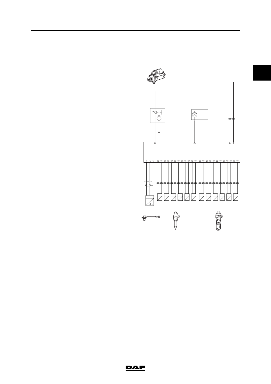
3.4 IMMOBILISER AND START INTERRUPTION

The complete control consists of three functions:

-

Fuel release immobiliser

-

Starter motor block immobiliser

-

Starter motor block if engine is running

Immobiliser

The task of the engine management system in 

the immobiliser system is to release and block the 

fuel supply and to block the starter motor. The 

purpose of the immobiliser is to ensure that the 

engine can only be started with the correct 

ignition key.

When the vehicle ignition is turned on, the 

immobiliser electronic unit reads the immocode 

from the ignition key and compares this to the 

codes (up to 5) stored in its memory. If the code 

is correct, the immobiliser electronic unit creates 

a coded CAN message and sends this via 

V-CAN1 to the DMCI electronic unit (D965). The 

DMCI electronic unit decrypts this CAN message 

using the stored vehicle code. If the vehicle code 

from the DMCI electronic unit and the vehicle 

code from the immobiliser electronic unit are 

identical, the CAN message is "approved".

The DMCI electronic unit releases the fuel supply 

by on-going control of the pump units and 

injectors.

If the codes do not match or there is a fault on the 

CAN connection, the DMCI electronic unit will 

block release of the fuel supply. The pump units 

and injectors will then no longer be activated. The 

DMCI electronic unit then informs the immobiliser 

unit that the code was not correct and a fault code 

is stored in the DMCI electronic unit and the 

immobiliser electronic unit.

On the second attempt to start the DMCI will not 

earth the starter motor (B010) via B09. The 

starter motor will therefore not work.

If release of the fuel supply is blocked, a red fault 

message is activated on the DIP master display, 

the "STOP" lamp lights up and an acoustic signal 

sounds. This message is sent via a CAN 

message and output B22 to VIC-2.

i400993

1 2

high-side

low-side

Cyl.6

B136

1 2

high-side

low-side

Cyl.5

B135

1 2

high-side

low-side

Cyl.4

B134

1 2

high-side

low-side

Cyl.3

B133

1 2

high-side

low-side

Cyl.2

B132

A3

A7

A12

A23

A24

A15

A8

A19

A16

A4

A11

A20

1 2

high-side

low-side

Cyl.1

Pump units

B131

1 2

high-side

low-side

Cyl.6

B426

1 2

high-side

low-side

Cyl.5

B425

1 2

high-side

low-side

Cyl.4

B424

1 2

high-side

low-side

Cyl.3

B423

1 2

high-side

low-side

Cyl.2

B422

1 2

high-side

low-side

Cyl.1

Injectors

B421

A2

A8

A9

A22

A21

A14

A5

A18

A13

A1

A10

A17

Vehicle

CAN1

low

Vehicle
CAN1
high

CAN1 low

CAN1 high

B35

B27

B09

flywheel housing

ground

Starter
motor

To battery +

To start
connector

B010

50a

50 30

31

M

B22

C20

+

D310

engine

warning

RED

VIC-2

shield

N

2 1

signal

return

3

F552

speed

crankshaft

A49

A50

A60

1

DMCI ENGINE MANAGEMENT SYSTEM

3-8

©

 200528

Control functions

XF105 series

Note:

Fuel is released as soon as an attempt is made to 

start the engine to promote a quick start. Release 

of the fuel supply will only be blocked if it 

becomes apparent that the codes do not match. 

So the engine may already be running before it is 

established that the codes do not match.

Starter motor lock

If the engine is running and the electronic unit 

DMCI receives an engine speed signal then 

DMCI will ensure that the starter motor can not be 

activated.

Relevant components
-

Pump units (B131 to B136)

-

Injectors (B421 to B426)

-

Starter motor (B010)

-

Immobiliser (D912 via V-CAN1)

1

©

 200528

3-9

Control functions

DMCI ENGINE MANAGEMENT SYSTEM

XF105 series

3.5 CYLINDER DETECTION AND SYNCHRONISATION

General
The electronic unit needs to know which cylinders 

are doing what and when in order to calculate the 

correct injection timing and the correct quantity of 

fuel to be injected for each cylinder. There are 3 

segments on the flywheel, which each have 18 

holes and an area with two holes missing. Each 

area with 2 holes missing indicates two cylinders 

that are at top dead centre at the same time (1/6, 

2/5 and 3/4). From the centre of the area where 

two holes are missing to the actual top dead 

centre of the cylinder, angle 

β (81 crankshaft = 

40.5

 camshaft) is covered. 13 pulses (72 

crankshaft) are emitted from the centre of hole 1 

to the centre of hole 13.

The camshaft has a pulse wheel with 6 teeth for 

cylinder detection and an additional tooth (S) for 

synchronisation. These 6 teeth for cylinder 

detection are spaced at 60

 intervals. The angle 

γ (15) between the synchronisation tooth and the 

cylinder -1 tooth on the camshaft pulse wheel 

correspond to angle 

γ (30) between the 14

th

 and 

15

th

 hole and the centre of the area where two 

holes are missing on the crankshaft.

α = 72 crankshaft (crankshaft sensor 1

st

 pulse)

β = 81 crankshaft = 40.5 camshaft (camshaft 

sensor on cylinder -1 pulse)

γ = 30 crankshaft = 15 camshaft (camshaft 

sensor on synchronisation pulse, crankshaft 

signal between 14

th

 and 15

th

 pulse of the 

previous segment)

i400996

D965

1 2

high-side

low-side

Cyl.6

B136

1 2

high-side

low-side

Cyl.5

B135

1 2

high-side

low-side

Cyl.4

B134

1 2

high-side

low-side

Cyl.3

B133

1 2

high-side

low-side

Cyl.2

B132

A3

A7

A12

A23

A24

A15

A8

A19

A16

A4

A11

A20

1 2

high-side

low-side

Cyl.1

Pump units

B131

1 2

high-side

low-side

Cyl.6

B426

1 2

high-side

low-side

Cyl.5

B425

1 2

high-side

low-side

Cyl.4

B424

1 2

high-side

low-side

Cyl.3

B423

1 2

high-side

low-side

Cyl.2

B422

1 2

high-side

low-side

Cyl.1

Injectors

B421

shield

N

1 2

signal

return

shield

3

F558

speed

camshaft

N

2 1

signal

return

3

F552

speed

crankshaft

A2

A8

A9

A22

A21

A14

A5

A18

A13

A1

A10

A17

A49

A50

A60

A53

A54

A61

TDC

13

18

15

14

1

18

CRANK

TDC

CAM

3

4

2

6

5

1

S

i4 00 707

1

DMCI ENGINE MANAGEMENT SYSTEM

3-10

©

 200528

Control functions

XF105 series

Synchronisation
The synchronisation procedure starts when the 

engine is being started. This procedure is a 

control for the electronic unit to detect the 

cylinders.

The procedure starts when the electronic unit 

detects a "hole" in the pulse train of the 

crankshaft sensor signal (F552). At that moment 

the electronic unit starts to count the crankshaft 

pulses and after the 14

th

 and 15

th

 pulse it 

immediately checks the camshaft signal (F558). If 

no camshaft signal is sent, the counting 

procedure is restarted after a "hole" in the 

crankshaft signal. 

CRANK

CAM

13

1

18

18

15

14

5

1

S

3

6

2

4

i4 00708


Content   ..  95  96  97  98   ..