DAF XF105. Manual - part 98


  Index      DAF     DAF XF105 - service repair manual


Search            


Content   ..  96  97  98  99   ..


DAF XF105. Manual - part 98


1

©

 200528

3-11

Control functions

DMCI ENGINE MANAGEMENT SYSTEM

XF105 series

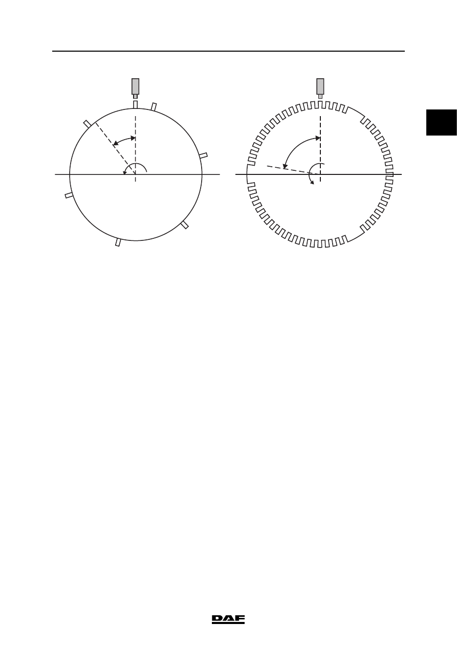
Synchronisation is complete when a camshaft 

pulse is sent by the camshaft sensor between the 

14

th

 and 15

th

 pulse of the crankshaft signal. This 

pulse is the synchronisation pulse (S). The 

synchronisation pulse must be detected within 

two crankshaft revolutions. If this is not the case, 

this indicates that something is wrong with the 

timing of the engine (mechanical fault) or with the 

sensor signals (electrical fault). If one of the 

sensor signals is absent, synchronisation cannot 

take place.

CRANK

CAM

13

1

18

18

15

14

5

1

S

3

6

2

4

i400709

1

DMCI ENGINE MANAGEMENT SYSTEM

3-12

©

 200528

Control functions

XF105 series

When synchronisation has taken place, the 

electronic unit can precisely determine which 

cylinder is doing what and when. The next pulse 

from the camshaft sensor after the 

synchronisation pulse (S) is that of cylinder 1. 

This matches the centre of the section of the 

flywheel in which two holes are missing (a "hole" 

in the crankshaft sensor signal). 

That is still 81

 before the actual top dead centre 

(TDC) of this cylinder. The electronic unit uses 

this period to make all the calculations for 

injection procedure, injection timing and injection 

quantity. 

CRANK

CAM

13

1

18

18

15

14

5

1

S

3

6

2

4

i400711

CRANK

CAM

13

1

18

18

15

14

5

1

S

3

6

2

4

i400710

1

©

 200528

3-13

Control functions

DMCI ENGINE MANAGEMENT SYSTEM

XF105 series

Emergency procedure when starting
If the crankshaft sensor signal is absent, the 

engine can still start but it takes a few revolutions 

longer. The camshaft signal is basically sufficient 

for cylinder detection. The electronic unit knows 

that the pulse for cylinder 1 follows the 

synchronisation pulse (S). In this case, the 

injection timing is calculated less precisely, 

because the crankshaft sensor pulses are 

absent. Injection must now be calculated on the 

basis of time.

If the camshaft signal is absent, the electronic 

unit cannot detect the various cylinders solely on 

the basis of the crankshaft sensor signal. 

The electronic unit therefore activates a pump 

unit/injector pair of a single arbitrary cylinder as if 

this is cylinder 1, a few degrees before each 13

th


crankshaft sensor pulse. The other pump unit / 

injector pairs are then activated in accordance 

with the injection sequence. If no crankshaft 

speed increase is observed by the electronic unit 

then it will select the next pump unit / injector pair 

and activate this as if it were cylinder 1. This has 

eventually to be the right pump unit / injector pair 

and an increase in the crankshaft speed will be 

observable. From then on, the electronic unit 

maintains the programmed injection sequence 

and the engine will start. In the worst case the 

recognition takes 12 crankshaft revolutions.

Emergency procedure when engine is 
running
If the camshaft sensor signal drops out when the 

engine is already running, this does not have any 

consequences for calculating injection. 

If the crankshaft sensor signal drops out when the 

engine is already running, the electronic unit can 

no longer precisely determine when the fuel must 

be injected. Only one pulse per cylinder is now 

received from the camshaft sensor. The 

electronic unit must now determine the correct 

injection timing on the basis of time.

Relevant components

-

Crankshaft sensor (F552)

-

Camshaft sensor (F558)

1

DMCI ENGINE MANAGEMENT SYSTEM

3-14

©

 200528

Control functions

XF105 series

3.6 FUEL INJECTION WHEN STARTING

If the "starting" status is detected on the basis of 

the starting speed, the coolant temperature 

(F566) and the engine speed are checked in 

order to calculate the required quantity of fuel and 

the injection timing. 

Use is made during starting of pilot injection. Pilot 

injection is a short injection before the main 

injection. The pressure build-up in the cylinder is 

more even because of this. This improves 

starting characteristics and decreases the 

emission of smoke.

If an increase in the engine speed is not detected 

after a short period (the engine does not start), 

the electronic unit will increase the quantity of fuel 

evenly in accordance with a calculated trajectory 

to a specific maximum. If the engine does not 

start then, a fault is stored.

The following applies for the injection timing: the 

higher the starting speed and the lower the 

coolant temperature, the earlier injection takes 

place.

Relevant components

-

Crankshaft sensor (F552)

-

Coolant temperature sensor (F566)

-

Pump units (B131 to B136)

-

Injectors (B421 to B426)

i401006

D965

1 2

high-side

low-side

Cyl.6

B136

1 2

high-side

low-side

Cyl.5

B135

1 2

high-side

low-side

Cyl.4

B134

1 2

high-side

low-side

Cyl.3

B133

1 2

high-side

low-side

Cyl.2

B132

A3

A7

A12

A23

A24

A15

A8

A19

A16

A4

A11

A20

1 2

high-side

low-side

Cyl.1

Pump units

B131

1 2

high-side

low-side

Cyl.6

B426

1 2

high-side

low-side

Cyl.5

B425

1 2

high-side

low-side

Cyl.4

B424

1 2

high-side

low-side

Cyl.3

B423

1 2

high-side

low-side

Cyl.2

B422

1 2

high-side

low-side

Cyl.1

Injectors

B421

shield

ground

T

R

1

signal

2

F566

temp.

coolant

N

2 1

signal

return

3

F552

speed

crankshaft

A2

A8

A9

A22

A21

A14

A5

A18

A13

A1

A10

A17

C26

C25

A49

A50

A60


Content   ..  96  97  98  99   ..