DAF XF105. Manual - part 96
1
©
200528
3-3
Control functions
DMCI ENGINE MANAGEMENT SYSTEM
XF105 series
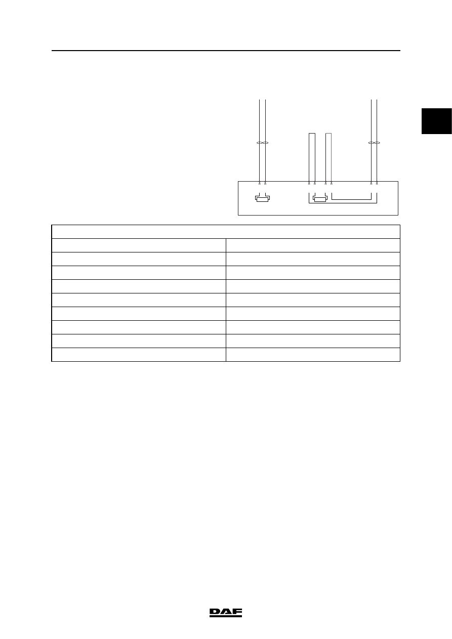
3.2 CAN CONTROLS
The DMCI engine management system
communicates via V-CAN1 and V-CAN2 with
various vehicle systems. DMCI is equipped with a
terminating resistor for V-CAN1 and V-CAN2.
The DMCI electronic unit receives relevant
information from other electronic units and sends
information to these electronic units in its turn.
Communication with DAVIE XD takes place via
the D-CAN to VIC-2 and via VIC-2 and V-CAN1
again to DMCI.
A number of important CAN messages are shown
below.
i400994
Vehicle
CAN2-low
Vehicle
CAN2-high
CAN2 low
CAN2 high
B42
B46
B53
B45
Vehicle
CAN1-low
Vehicle
CAN1-high
CAN1 low
CAN1 high
B35
B27
B50
B54
R
R
D965
DMCI
V-CAN1
V-CAN2
VIC-2
VIC-2
EAS
DIP-4
AS Tronic
BBM
Immobiliser
MTCO / DTCO
ZF retarder EST-42
ABS-D
EBS-2
ECAS-4