DAF XF105. Manual - part 95
1
©
200528
2-29
Description of components
DMCI ENGINE MANAGEMENT SYSTEM
XF105 series
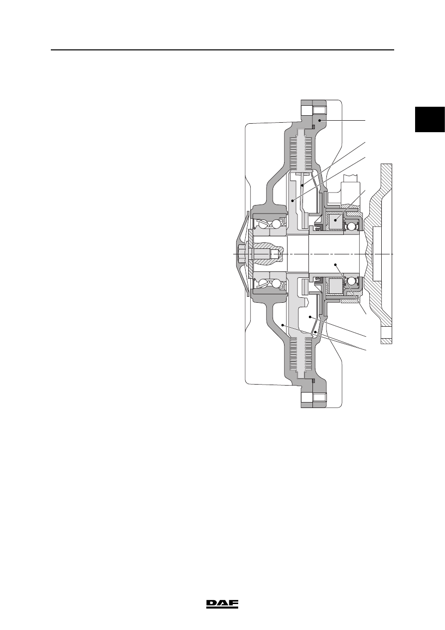
Fan clutch actuated
If the coil (4) is actuated by way of a duty-cycle
then the lid (2) will be attracted by the magnetism
created. The filler opening is then closed by the
lid (2) and at the same time the return opening is
opened up. The silicon fluid now flows from the
working area (7) between the stator (1) and the
rotor (3) to the supply chamber (6). Less silicon
fluid in the working area means more slip
between the stator (1) and the rotor (3). The fan
speed will decrease.
Note:
Duty cycle high means decreasing fan speed.
Duty cycle low means increasing fan speed.
Actuated
1
2
3
4
5
6
7
i401013