DAF XF105. Manual - part 94


  Index      DAF     DAF XF105 - service repair manual


Search            


Content   ..  92  93  94  95   ..


DAF XF105. Manual - part 94


1

©

 200528

2-25

Description of components

DMCI ENGINE MANAGEMENT SYSTEM

XF105 series

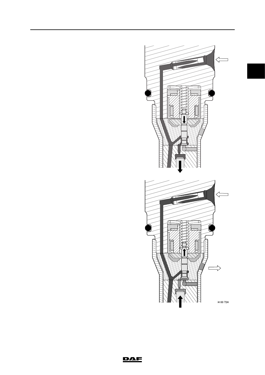
Even though fuel is now being supplied to the 

injector, this does not mean that it immediately 

starts injecting. The same fuel pressure that must 

lift the injector needle also pushes down the 

plunger - along with the plunger spring. The 

injector needle cannot yet be lifted.

When the coil is activated by the electronic unit, 

the valve is pulled in against the pressure of the 

spring and the opening to the return is released. 

As a result, the pressure above the plunger 

decreases. The fuel pressure under the injector 

needle now overcomes the pressure of the spring 

above the plunger. The injector needle is lifted 

and fuel is injected.

To stop injection, the fuel supply pressure to the 

injector is decreased by deactivating the pump 

unit. The injector is only deactivated once the fuel 

pressure is low enough. This is to allow the 

plunger spring to close the injector needle 

quickly.

i4 00 723

1

DMCI ENGINE MANAGEMENT SYSTEM

2-26

©

 200528

Description of components

XF105 series

Every injector is calibrated during production to 

compensate for any inaccuracies/differences in 

production. There is a 6-letter calibration code on 

the housing of the electrical connections. The 

code must be programmed into the electronic unit 

so that the unit can optimise controls for fuel 

injection. As a result, the electronic unit can 

ensure that the injection timing and the quantity of 

fuel injected do not differ. If the injector is 

replaced or moved, the calibration code must 

be programmed into the electronic unit using 

DAVIE XD.

i400772

1

©

 200528

2-27

Description of components

DMCI ENGINE MANAGEMENT SYSTEM

XF105 series

2.13 ELECTRONICALLY CONTROLLED FAN CLUTCH

An electronically controlled fan clutch is used for 

accurate control of the fan speed.

The electronically controlled fan clutch checks 

and controls the fan speed to ensure that the flow 

of cooling air through the cooling system is 

sufficient to keep the coolant temperature and/or 

inlet air temperature within certain limits.

The coil (4) fitted to the drive shaft (5) with 

bearings generates a magnetic field. The duty 

cycle to the coil (4) will be modified depending on 

the variables stated above. This will cause 

changes in the magnetic field and the valve (2) 

will be attracted either more or less.

Control of the fan clutch depends on various 

factors:

-

coolant temperature

-

the inlet air temperature

-

vehicle speed

-

engine speed

-

fan  speed

-

intarder activation

-

internal slip of the fan clutch (slip heat 

protection)

The fan clutch consists of a stator (1) and the 

rotor (3), which is fixed to the drive shaft (5). It 

also includes the supply chamber (6) for the 

silicone fluid.

The working area is located between the 

stator (1) and the rotor (3). The fan is fitted to 

the stator (1) and rotates freely around the drive 

shaft (5).

The speed of the fan is sensed by an internal Hall 

sensor and a pulse disc.

This sensor sends a signal to the electronic unit 

DMCI. The electronic unit uses this signal to 

check the internal slip of the fan and the response 

to controls.

1

2

3

4

5

6

7

i401012

1

Stator

2

lid

3

Rotor

4

Coil

5

Drive shaft

6

Supply chamber

7

Working area

1

DMCI ENGINE MANAGEMENT SYSTEM

2-28

©

 200528

Description of components

XF105 series

Operation

Fan clutch not actuated
The lid (2) is now in the original position. The filler 

opening is now released and the return opening 

is closed. The quantity of silicon fluid through the 

working area (7) between the stator (1) and the 

rotor (3) increases because of this. The friction in 

the working area between the stator (1) and the 

rotor (3) will increase and the difference in 

rotating speed (slip) between the stator (1) and 

the rotor (3) will decrease. The fan speed is 

increased because of this. The fan speed will 

approach or exceed the engine speed depending 

on the transmission between the crankshaft and 

the fan drive.

Note:

This therefore means that in the event of the 

failure of the actuation of the fan clutch the fan will 

turn at maximum speed.

Not actuated

1

2

3

4

5

6

7

i401012


Content   ..  92  93  94  95   ..