DAF XF105. Manual - part 92
1
©
200528
2-17
Description of components
DMCI ENGINE MANAGEMENT SYSTEM
XF105 series
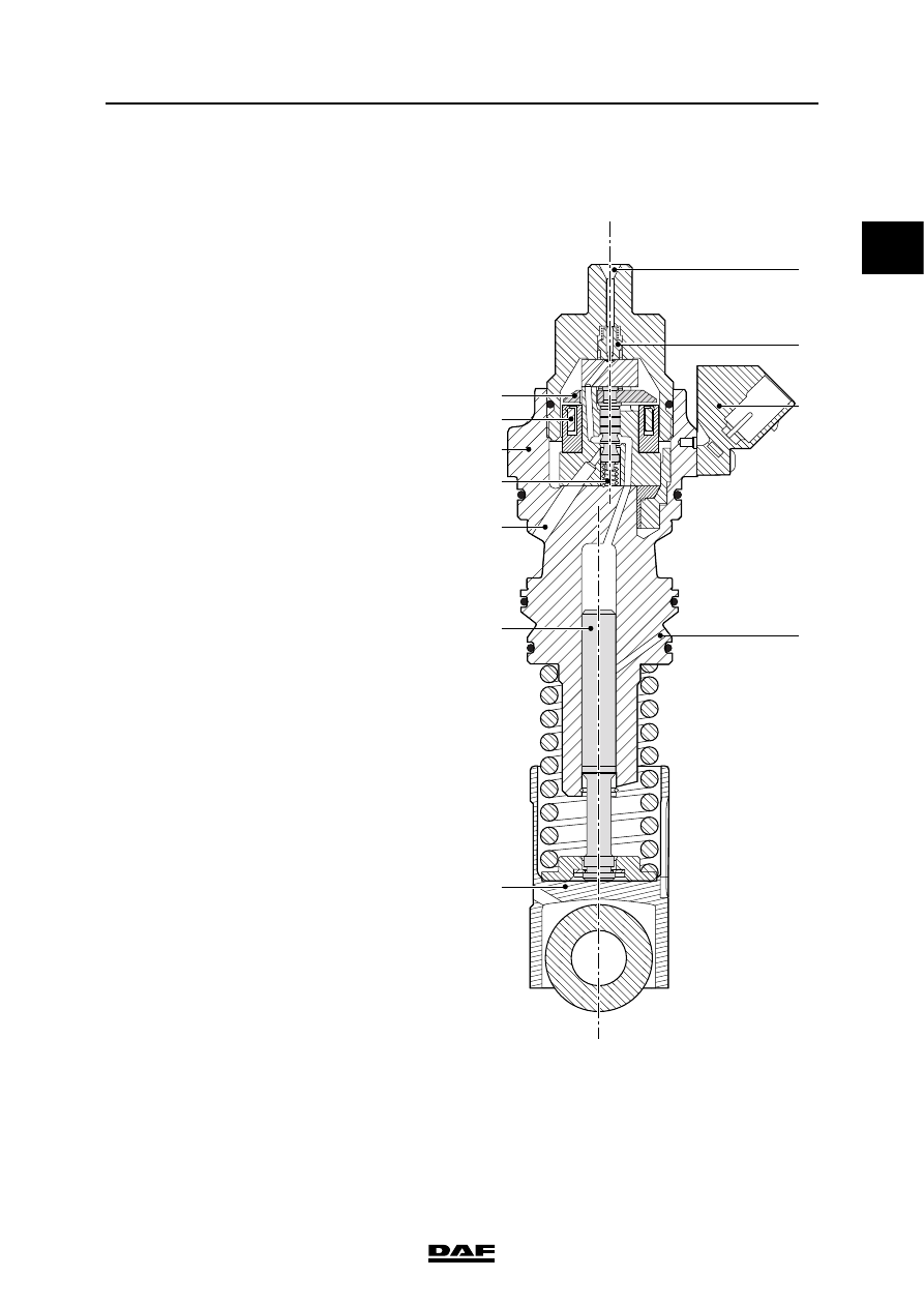
2.11 PUMP UNIT
General
The pump unit supplies fuel to the injector. The
pump unit consists of a metal housing (3) in
which an electrical coil (2) opens a valve (1). In
the rest position, the valve (1) is pushed up by a
spring (4). The electrical connection (8) is
screwed onto the outside of the pump unit. The
roller tappet (6) rotates around the camshaft and
actuates the plunger (5), which builds up the fuel
pressure. The fuel enters the pump unit via the
fuel gallery opening (A). This opening goes into
the fuel supply gallery in the engine block. The
fuel leaves the pump unit in the direction of the
injector via a delivery valve (7). The fuel pipe is
fitted to the injector supply connection (C). Leak-
off/lubricating fuel from the plunger is fed back to
the return gallery in the engine block via the
return opening (B).
B
C
A
1
2
3
4
5
6
8
7
i4 00 714
A.
Fuel gallery opening
B.
Return opening
C.
Injector inlet connection
1.
Lid
2.
Coil
3.
Pump unit housing
4.
Spring
5.
Plunger
6.
Roller tappet
7.
Delivery valve
8.
Electrical connection