DAF XF105. Manual - part 90


  Index      DAF     DAF XF105 - service repair manual


Search            


Content   ..  88  89  90  91   ..


DAF XF105. Manual - part 90


1

©

 200528

2-9

Description of components

DMCI ENGINE MANAGEMENT SYSTEM

XF105 series

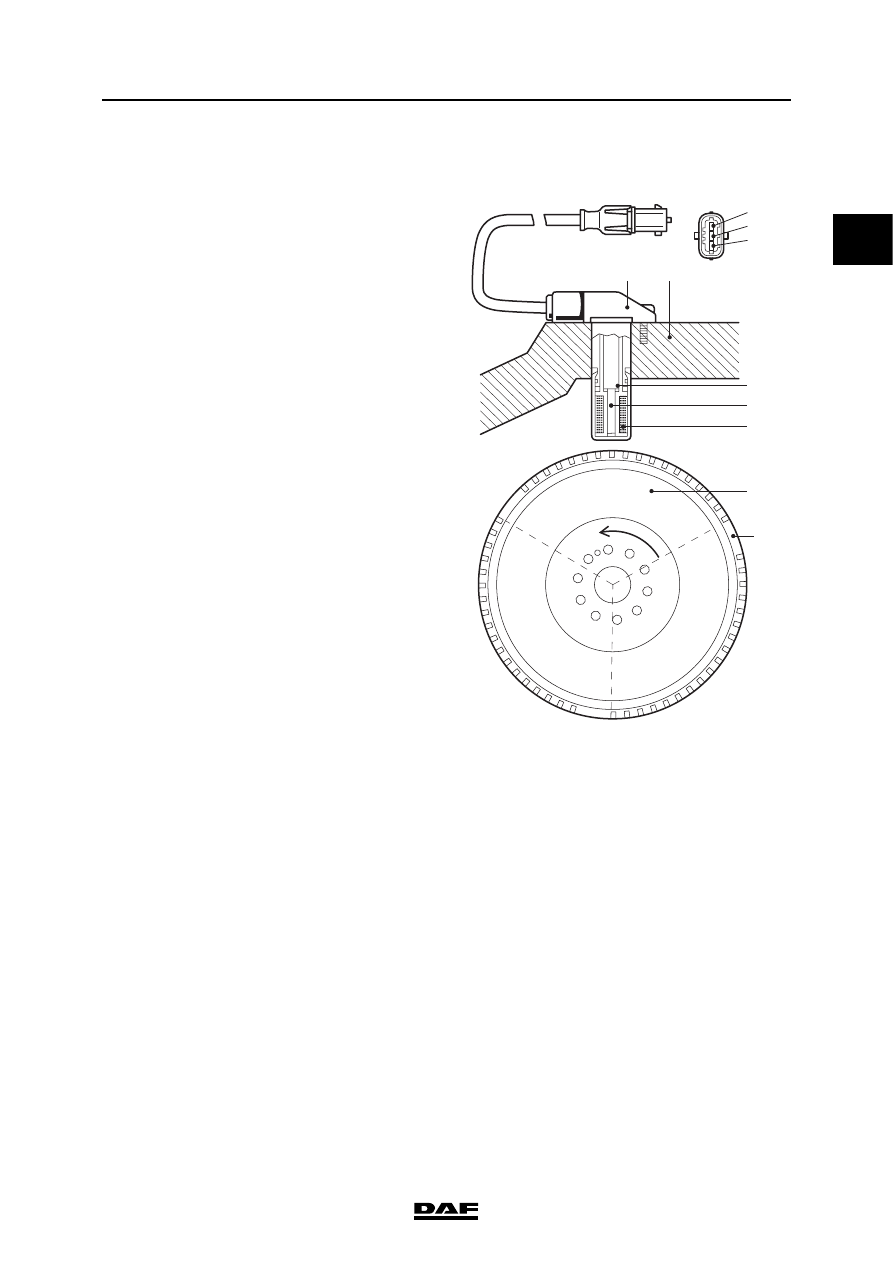
2.8 CRANKSHAFT SENSOR

The crankshaft sensor (F552) registers engine 

speed and is used to determine the injection 

timing. The crankshaft sensor is responsible, 

together with the camshaft sensor, for 

synchronisation when starting the engine. If there 

is no camshaft signal, the crankshaft signal is 

used for cylinder detection.

The crankshaft sensor (A) is mounted on the 

flywheel housing (B). It is an inductive sensor and 

consists of a magnet (C), a metal core (D) and a 

coil (E). Inductive means that the sensor can 

generate an alternating voltage signal 

independently by means of a changing magnetic 

field. The pattern of holes in the flywheel (F) 

means that the sensor can generate a specific 

alternating signal. The pattern consists of 3 

segments each with 18 holes and an area with 

2 holes missing (G). Each segment is used for 

calculations on two specific cylinders (1/6, 2/5 

and 3/4).

The sensor has 3 connections. Pins 1 and 2 are 

responsible for the signal. Pin 2 is the signal 

connection and pin 1 is the earth connection. Pin 

3 is connected to the shield around the signal 

wires and to the earth connection (pin 1). This 

prevents the engine speed signal being affected 

by signals from outside. 

1

18

I400731

1

2

3

A

B

N

S

D

C

E

F

G

1

Electrical connection, earth

2

Electrical connection, signal

3

Electrical connection, shield

A

Crankshaft sensor

B

Flywheel housing

C

Magnet

D

Metal core

E

Coil

F

Flywheel

G

Hole pattern

1

DMCI ENGINE MANAGEMENT SYSTEM

2-10

©

 200528

Description of components

XF105 series

The most powerful changes in the magnetic field 

of the sensor take place when the pattern of holes 

(1) in the flywheel changes from a hole to a tooth 

and vice versa. A sine-wave alternating voltage 

(2) is generated as a result of this changing 

magnetic field. As a hole approaches, the 

crankshaft sensor signal must be at the maximum 

positive value and then drop to the maximum 

negative value as the end of the hole 

approaches. This is determined by the sensor 

connections to the electronic unit! The electronic 

unit converts this sine-wave alternating voltage 

signal to a digital signal (3) which it uses to carry 

out calculations.

E500606

1

2

3

1

I400732

2

a

b

c

1

©

 200528

2-11

Description of components

DMCI ENGINE MANAGEMENT SYSTEM

XF105 series

Sine-wave signals (2) can be measured using an 

oscilloscope with the engine running using the 

pattern of holes in the flywheel (1). Each hole in a 

segment (b) generates a sine-wave pulse. When 

the area with the two holes missing (a and c) goes 

under the crankshaft sensor, the pulse pattern is 

interrupted. This enables the sensor to detect the 

end of the segment. 

Effect of output signal on the system:
-

synchronisation during starting;

-

injection timing calculation;

-

registration of engine speed;

-

cylinder detection if there is no camshaft 

signal.

-

CAN message engine speed to other vehicle 

systems via V-CAN1 (AS Tronic, EAS) and 

V-CAN2 (VIC-2, ZF intarder EST-42, ABS-D, 

EBS-2, DIP-4, ECAS-4, builder module)

-

output signal engine speed (EMAS, cab 

lead-through connector).

1

DMCI ENGINE MANAGEMENT SYSTEM

2-12

©

 200528

Description of components

XF105 series

2.9 CAMSHAFT SENSOR

The camshaft sensor (F558) is responsible, 

together with the crankshaft sensor, for 

synchronisation when starting the engine. The 

signal also provides the information relating to 

cylinder detection. If the crankshaft sensor (F552) 

is defective the camshaft signal acts as a reserve 

signal for registering the engine speed and 

determining the correct injection timing.

The camshaft sensor (A) is mounted on the 

flywheel housing (B). It is an inductive sensor and 

consists of a magnet (C), a metal core (D) and a 

coil (E). Inductive means that the sensor can 

generate an alternating voltage signal 

independently by means of a changing magnetic 

field. The sensor can generate a specific 

alternating signal by means of a tooth pattern on 

the pulse wheel (F). The sensor has 3 

connections. Pins 1 and 2 are responsible for the 

signal. Pin 1 is the signal connection and pin 2 is 

the earth connection. Pin 3 is connected to the 

shield around the signal wires and to the earth 

connection (pin 2). This prevents the signal being 

affected by signals from outside.

I400761

C
D
E

N

S

F

3

6

2

4

S

1

5

A

B

1

2

3

1

Electrical connection, signal

2

Electrical connection, earth

3

Electrical connection, shield

A

Camshaft sensor

B

Flywheel housing

C

Magnet

D

Metal core

E

Coil

F

Pulse wheel


Content   ..  88  89  90  91   ..