DAF XF105. Manual - part 88


  Index      DAF     DAF XF105 - service repair manual


Search            


Content   ..  86  87  88  89   ..


DAF XF105. Manual - part 88


1

©

 200528

2-1

Description of components

DMCI ENGINE MANAGEMENT SYSTEM

XF105 series

2. DESCRIPTION OF COMPONENTS

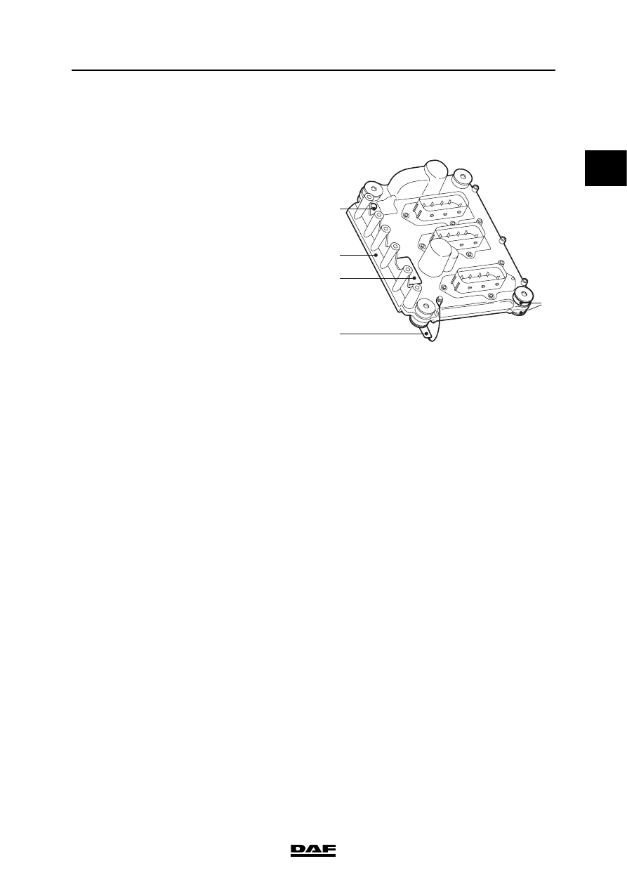
2.1 DMCI ELECTRONIC UNIT

The electronic unit is mounted on the cylinder 

block using rubber insulating bushes (3). The 

electronic unit has three 62-pin connectors. Input 

signals from various sensors are continuously 

processed and compared with data stored in 

various maps (tables) in the electronic unit.

Actuators are energised on the basis of the 

signals received and the maps.

The housing (1) of the electronic unit is directly 

connected to the engine block by an earth cable 

(2). This earth connection is required because of 

internal components which protect against radio 

waves from outside.

The electronic unit incorporates an atmospheric 

pressure sensor and a temperature sensor. 

There is an air vent (4) for the atmospheric 

pressure sensor in the housing of the electronic 

unit.

An identification sticker (5) is attached to the 

electronic unit. 

The effect of atmospheric pressure on the 
system:
-

the quantity of fuel injected when driving at 

high altitudes (low air pressure).

If atmospheric pressure is low (in mountainous 

areas), the air is thinner. When the air is thinner it 

has a low density. The electronic unit uses this 

information to control the turbocharger pressure 

and adjust the quantity of fuel to be injected.

The effect of the internal temperature sensor 
on the system:
-

none.

The internal temperature sensor measures the 

temperature of the electronic unit. If the 

temperature becomes too high, a fault code is 

stored. The system does not take any further 

action on the basis of this information.

Calibration

The performance of pump units and injectors may 

differ slightly from one another as a result of small 

production tolerances. These small production 

differences are compensated for during 

production by means of calibration in order to 

optimise the engine output, exhaust gas 

emissions and handling characteristics. A 

calibration code is used to program the pump 

units and injectors into the electronic unit 

individually. The electronic unit modifies the 

control of the pump units and injectors on the 

basis of these calibration codes.

i400785

1

5

2

3

4

1

DMCI ENGINE MANAGEMENT SYSTEM

2-2

©

 200528

Description of components

XF105 series

2.2 ACCELERATOR PEDAL SENSOR

The accelerator pedal sensor (F672) is mounted 

on the accelerator pedal. The sensor (2) consists 

of a potentiometer and a switch.

Potentiometer

The output signal (B33) from the potentiometer is 

a linear voltage that has a fixed relationship with 

the position of the accelerator pedal and 

therefore is determined by the driver. The 

potentiometer signal is the basis for determining 

the quantity of fuel to be injected. The 

potentiometer has a supply voltage (B34) and an 

earth (B37) via the electronic unit.

Idling switch

Parallel to the potentiometer also the idling switch 

is operated by depressing the accelerator pedal. 

The idling switch is open in the no-load position 

and is closed when the accelerator pedal is 

operated. The switch is required for the 

emergency function, when the potentiometer 

signal is absent. This emergency function allows 

the vehicle to be driven to a safe place or a 

workshop if there is no potentiometer signal. One 

side of the switch is connected to earth (B38) via 

the electronic unit. The positive side (B41) is 

connected to earth by means of the switch. 

Kick-down switch

The kick-down switch (1) under the accelerator 

pedal only acts to form a mechanical resistance 

when the accelerator pedal is depressed. The 

electronic unit detects the kick-down status 

because the value of the output signal from the 

potentiometer is higher than at full load. The kick-

down switch is for instance used to temporarily 

disengage variable vehicle speed limiting so that 

an automatic/automated gearbox can shift down 

(in order to accelerate).

D965

F672

2

1

i400694

B34

C

A

B

D

F

4677

4679

4678

4166

4680

B33

B37

B38

B41

1

Kick-down switch

2

Accelerator pedal sensor

1

©

 200528

2-3

Description of components

DMCI ENGINE MANAGEMENT SYSTEM

XF105 series

Effect of potentiometer output signal on the 
system:
-

the basis for determining the quantity of fuel 

to be injected.

-

engine brake disengaging/engaging 

conditions

-

disengaging conditions of Downhill Speed 

Control

-

CAN message accelerator pedal position, 

via V-CAN1 (AS Tronic, AGC-A) and 

V-CAN2 (EBS-2, VIC-2, builder module);

-

CAN message kickdown position active, via 

V-CAN1 (AS Tronic, AGC-A);

Effect of idling switch output signal on the 
system:
-

emergency function if the potentiometer is 

not working.

-

engine brake disengaging/engaging 

conditions

-

disengaging conditions of Downhill Speed 

Control

-

CAN message idling switch active, via 

V-CAN1 (AS Tronic) and V-CAN2 (VIC-2, 

ZF intarder EST-42, EBS-2, DIP-4, builder 

module)

1

DMCI ENGINE MANAGEMENT SYSTEM

2-4

©

 200528

Description of components

XF105 series

2.3 COOLANT TEMPERATURE SENSOR

The coolant temperature sensor emits a signal 

that indicates the temperature of the coolant and 

therefore indirectly the engine temperature. The 

sensor used is of the NTC (negative temperature 

coefficient) type. The higher the temperature, the 

lower the resistance of the sensor.

Effect of output signal on the system:
-

calculation of glowing time;

-

calculation of the quantity of fuel to be 

injected and the injection timing;

-

calculation of actuation of the electronically 

controlled fan clutch;

-

limiting of engine torque when temperature is 

too high;

-

CAN message engine temperature, via 

V-CAN2 to VIC-2 for display on the 

instrument panel;

-

limitation of the maximum engine speed 

when the engine is cold.

2.4 2

nd

 COOLANT TEMPERATURE SENSOR

The 2

nd

 coolant temperature sensor (F743) gives 

a signal of the temperature of the coolant and 

therefore indirectly of the engine at the level of 

cylinder 6. The signal is compared by the 

electronic unit (D965) to the signal from the 

coolant sensor (F566) at the level of cylinder 1. 

The sensor is of the NTC (Negative Temperature 

Coefficient) type. The higher the temperature, the 

lower the resistance of the sensor.

Effect of the signal on the system:
-

Detection of a cooling problem resulting in 

engine torque limitation

i 400440

i401003


Content   ..  86  87  88  89   ..