DAF XF105. Manual - part 89


  Index      DAF     DAF XF105 - service repair manual


Search            


Content   ..  87  88  89  90   ..


DAF XF105. Manual - part 89


1

©

 200528

2-5

Description of components

DMCI ENGINE MANAGEMENT SYSTEM

XF105 series

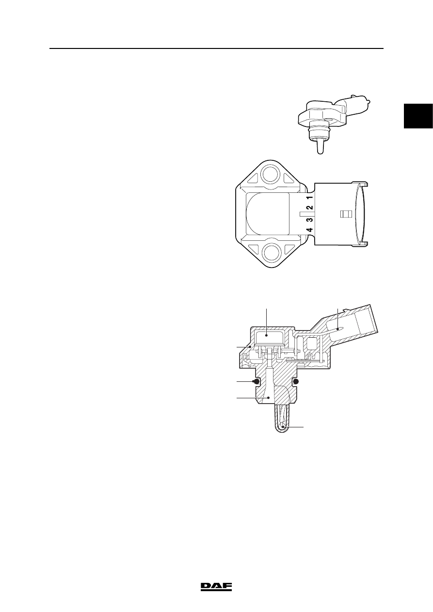
2.5 INLET AIR BOOST PRESSURE AND TEMPERATURE SENSOR

This is a combined sensor that measures the air 

pressure in the inlet manifold and the 

temperature of this air. The electronic unit uses 

this data to calculate the quantity of air drawn in. 

The quantity of intake air needs to be known in 

order to calculate the quantity of injected fuel to 

prevent smoke. The charge pressure is also in a 

direct relationship to the turbocharger pressure 

control. The waste gate valve is actuated 

depending on this signal. 

The charge temperature sensor (3) used is of the 

NTC (negative temperature coefficient) type. The 

higher the temperature, the lower the resistance 

of the sensor. The charge pressure sensor (1) is 

a piezoresistive sensor. The inlet air is measured 

via an opening (4) in the sensor. The higher the 

pressure, the higher the voltage signal. The 

sensor is sealed in the installation hole in the 

cylinder head by an O-ring (5).

i 400441

i400742

1

2

3

4

5

6

1

Air inlet pressure sensor, piezo-resistive

2

Electrical connection

3

Air inlet temperature sensor, NTC

4

Air inlet opening

5

O-ring

6

Accommodation

1

DMCI ENGINE MANAGEMENT SYSTEM

2-6

©

 200528

Description of components

XF105 series

The temperature signal is fed back to the 

electronic unit via a connection (2).

A piezoresistive sensor requires a power 

supply (3) and earth (1) to create a linear 

voltage signal (4). 

Effect of temperature signal on the system:
-

calculation of glowing time;

-

correction on the waste gate control;

-

correction on the smoke limiting system.

Effect of pressure signal on the system:
-

calculation for smoke limiting;

-

calculation of the waste gate control;

-

protection of turbocharger;

-

CAN message to VIC for the charge boost 

pressure display on the main display of 

the DIP.

P

U

T

R

3

4

2

1

i400534

1

©

 200528

2-7

Description of components

DMCI ENGINE MANAGEMENT SYSTEM

XF105 series

2.6 FUEL PRESSURE AND TEMPERATURE SENSOR

This is a combined sensor that measures the fuel 

pressure in the fuel gallery and the temperature 

of this fuel. The sensor is located in the middle of 

the fuel gallery between the cylinder 3 pump unit 

and the cylinder 4 pump unit. Because of this the 

measured values for fuel pressure and 

temperature are the most representative for the 

whole fuel gallery.

The fuel temperature sensor is of the NTC 

(negative temperature coefficient) type. The 

higher the temperature, the lower the resistance.

The fuel pressure sensor is a Piëzo capacitive 

sensor. The higher the pressure, the higher the 

voltage signal.

The temperature signal is fed back to the 

electronic unit via a connection (3).

A Piëzo capacitive sensor requires a power 

supply (1) and earth (4) to create a linear voltage 

signal (2).

Effect of temperature signal on the system:
-

correction of quantity of fuel to be injected;

-

calculation of glowing time;

Effect of pressure signal on the system:
-

enabling fuel pressure to be read on DAVIE;

1

3

4

2

i400792

P

U

T

R

2

1

3

4

i400791

1

DMCI ENGINE MANAGEMENT SYSTEM

2-8

©

 200528

Description of components

XF105 series

2.7 ENGINE OIL PRESSURE AND TEMPERATURE SENSOR

This is a combined sensor that measures the 

engine oil pressure in the cylinder block main 

passage and the temperature of this oil. 

The engine oil temperature sensor used is of the 

NTC (negative temperature coefficient) type. The 

higher the temperature, the lower the resistance 

of the sensor. The engine oil pressure sensor is a 

Piëzo capacitive sensor. The higher the pressure, 

the higher the voltage signal. The engine oil 

pressure is measured via an opening in the 

sensor. The higher the pressure, the higher the 

voltage signal.

The temperature signal is fed back to the 

electronic unit via a connection (3). A piëzo-

capacitive sensor requires a power supply (1) 

and earth (4) to create a linear voltage signal (2).

Effect of temperature signal on the system:
-

none.

Effect of pressure signal on the system:
-

CAN message to VIC to actuate oil pressure 

indicator light and warning on the DIP main 

display when engine oil pressure is too low.

1

3

4

2

i400792

P

U

T

R

2

1

3

4

i400791


Content   ..  87  88  89  90   ..