Chrysler Town, Dodge Caravan. Manual - part 387


  Index      Chrysler     Chrysler TOWN & COUNTRY, VOYAGER, Dodge Caravan - service repair manual 2001-2007 year


Search            


Content   ..  385  386  387  388   ..


Chrysler Town, Dodge Caravan. Manual - part 387


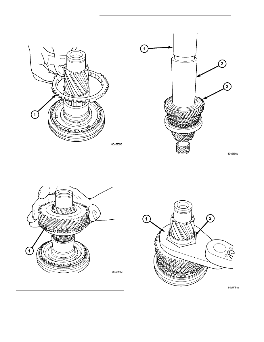
(7) Install 4th gear blocker ring (Fig. 220).

(8) Install

4th

gear

and

needle

bearing

(if

equipped) (Fig. 221).

(9) Install 5th gear and press into position using

installer 8481 (Fig. 222).

(10) Install NEW 5th gear nut and torque to 262

N·m (193 ft. lbs.) using wrench 8478 (Fig. 223).

Fig. 220 4th Gear Blocker Ring

1 - 4th GEAR BLOCKER RING

Fig. 221 4th Gear Removal/Installation

1 - 4th GEAR

Fig. 222 5th Gear Installation

1 - ARBOR PRESS RAM
2 - INSTALLER 8481
3 - 5TH GEAR

Fig. 223 5th Gear Nut Removal/Installation

1 - WRENCH 8478
2 - 5TH GEAR NUT

21 - 98

T850 MANUAL TRANSAXLE

RS

INPUT SHAFT (Continued)

(11) Stake 5th Gear nut in four (4) places as fol-

lows:

(a) Install staking tool 8479 to 5th gear nut.
(b) Tighten upper thumb screw by hand (Fig.

224).

(c) Tighten two (2) side thumb screws by hand.
(d) Tighten both staking screws until they bot-

tom on tool body (Fig. 225).

(e) Loosen staking screws and thumb screws.

Remove tool and visually inspect stake (Fig. 226).

(f) Remove tool, rotate 90°, and repeat process to

stake in four (4) places.

NOTE: The input shaft sealed roller bearing and
snap ring do not get installed until transaxle assem-
bly to facilitate installation of the reverse idler gear
mechanism.

Fig. 224 Staking Tool Set-Up

1 - STAKING TOOL 8479
2 - THUMB SCREWS (3)

Fig. 225 Tighten Stake Screws

1 - STAKING TOOL 8479

Fig. 226 5th Gear Nut Stake (Four Places)

1 - STAKE

RS

T850 MANUAL TRANSAXLE

21 - 99

INPUT SHAFT (Continued)

INTERMEDIATE SHAFT

DESCRIPTION

The intermediate shaft assembly (Fig. 227) is part

of the transaxle geartrain, meshes with and is driven
by the input shaft, drives the differential via an inte-
grated pinion gear, and consists of the following com-
ponents:

• Intermediate Mainshaft

• 1st Speed Gear

• 2nd Speed Gear

• 3/4 Cluster Gear

• 5th Speed Gear

• Reverse Gear

• 1/2 Synchronizer

• 5/R Synchronizer
The intermediate shaft is supported by a caged

roller bearing at the front of the transaxle, and a
sealed roller bearing at the rear of the transaxle.

DISASSEMBLY

CAUTION: Do not re-use snap rings when servicing
the intermediate shaft assembly. Discard upon dis-
assembly and install new ones provided with avail-
able snap ring service kit.

NOTE: Depending on date of transaxle manufacture,
some intermediate shafts will utilize a needle bear-
ing under the 2nd and 5th Speed Gears.

(1) Install intermediate shaft assembly to arbor

press table with bearing splitter P-334 under the
reverse gear.

Fig. 227 Intermediate Shaft Assembly

1 - INTERMEDIATE SHAFT

10 - SNAP RING

2 - ROLLER BEARING

11 - SEALED ROLLER BEARING

3 - SNAP RING

12 - THRUST WASHER

4 - NEEDLE BEARING

13 - NEEDLE BEARING

5 - 1ST SPEED GEAR

14 - REVERSE GEAR

6 - SNAP RING

15 - SNAP RING

7 - 2ND SPEED GEAR

16 - 5/R SYNCHRO

8 - 3/4 CLUSTER GEAR

17 - 5TH SPEED GEAR

9 - SNAP RING

18 - 1/2 SYNCHRO

21 - 100

T850 MANUAL TRANSAXLE

RS

(2) Install 8486-4 button to intermediate shaft.

Using arbor press ram, press reverse gear and inter-
mediate roller bearing off of shaft, while holding
remaining assembly with hand (Fig. 228).

(3) Remove reverse gear blocker ring.
(4) Remove reverse gear needle bearing (Fig. 229).

(5) Remove 5/R synchro snap ring (Fig. 230).

(6) Remove 5/R synchro (Fig. 231).

Fig. 228 Bearing and Reverse Gear Removal

1 - ARBOR PRESS RAM
2 - ADAPTER 8486-4
3 - SEALED ROLLER BEARING
4 - REVERSE GEAR
5 - BEARING SPLITTER P-334

Fig. 229 Reverse Gear Needle Bearing

1 - NEEDLE BEARING

Fig. 230 5/R Synchro Snap Ring

1 - SNAP RING

Fig. 231 5/R Synchronizer

1 - 5/R SYNCHRO ASSEMBLY

RS

T850 MANUAL TRANSAXLE

21 - 101

INTERMEDIATE SHAFT (Continued)


Content   ..  385  386  387  388   ..