Chrysler Town, Dodge Caravan. Manual - part 349


  Index      Chrysler     Chrysler TOWN & COUNTRY, VOYAGER, Dodge Caravan - service repair manual 2001-2007 year


Search            


Content   ..  347  348  349  350   ..


Chrysler Town, Dodge Caravan. Manual - part 349


on the threads and do not require an additional coat-
ing.

(2) Install sensor and tighten to 27 N·m (20 ft.

lbs.) (Fig. 23).

(3) Connect the electrical connector for the O2 sen-

sor and install onto bracket.

(4) Lower vehicle.
(5) Connect the negative battery cable.

INSTALLATION - UPSTREAM 1/1 - 3.3/3.8L

The engines uses two heated oxygen sensors.

(1) After removing the sensor, the exhaust mani-

fold threads must be cleaned with an 18 mm X 1.5 +
6E tap. If reusing the original sensor, coat the sensor
threads with an anti-seize compound such as Loctite
771- 64 or equivalent. New sensors have compound
on the threads and do not require an additional coat-
ing.

(2) Install sensor and tighten to 27 N·m (20 ft.

lbs.).

(3) Connect the electrical connector for the O2 sen-

sor and install onto bracket.

(4) Connect the electrical connector for the speed

control servo.

(5) Install the speed control servo and bracket

refer to the Speed Control Servo for more informa-
tion.

(6) Connect the speed control vacuum harness to

servo.

(7) Install the battery tray, refer to the Battery

section for more information.

(8) Install battery, refer to the Battery section for

more information.

INSTALLATION DOWNSTREAM 2/1 -
2.4/3.3/3.8L

The O2S is located on the side of the catalytic con-

verter.

Threads of new oxygen sensors are factory coated

with anti-seize compound to aid in removal. DO
NOT add any additional anti-seize compound to
the threads of a new oxygen sensor.

(1) Install sensor and tighten to 27 N·m (20 ft.

lbs.).

(2) Connect the electrical connector.
(3) Lower vehicle.
(4) Install the negative battery cable.

THROTTLE BODY

DESCRIPTION

The throttle body is located on the intake manifold

(Fig. 28) or (Fig. 29). Fuel does not enter the intake
manifold through the throttle body. Fuel is sprayed
into the manifold by the fuel injectors.

OPERATION

Filtered air from the air cleaner enters the intake

manifold through the throttle body. The throttle body
contains an air control passage controlled by an Idle
Air Control (IAC) motor. The air control passage is
used to supply air for idle conditions. A throttle valve
(plate) is used to supply air for above idle conditions.

Certain sensors are attached to the throttle body.

The accelerator pedal cable, speed control cable and

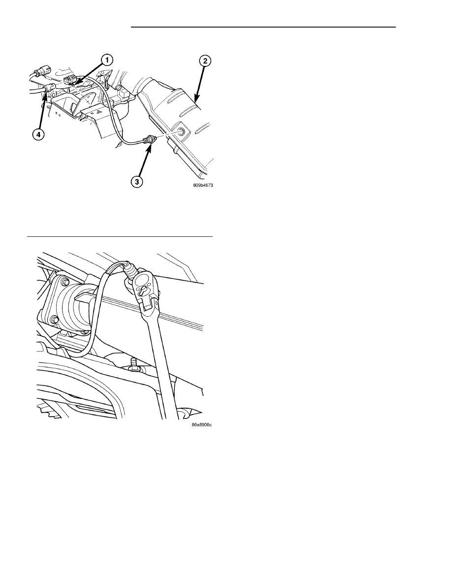
Fig. 26 Downstream Oxygen Sensor (1/2)

1 - OXYGEN SENSOR CONNECTOR
2 - CATALYTIC CONVERTER
3 - DOWNSTREAM OXYGEN SENSOR
4 - ENGINE HARNESS CONNECTOR

Fig. 27 DOWNSTREAM 2/1 O2 SENSOR

14 - 34

FUEL INJECTION

RS

O2 SENSOR (Continued)

transmission control cable (when equipped) are con-
nected to the throttle body linkage arm.

A (factory adjusted) set screw is used to mechani-

cally limit the position of the throttle body throttle
plate. Never attempt to adjust the engine idle
speed using this screw. 
All idle speed functions are
controlled by the PCM.

REMOVAL

(1) Disconnect negative cable from battery cable.
(2) Remove air inlet to throttle body hose clamp.

(3) Remove throttle and the speed control (if

equipped) cables from lever and bracket.

(4) Disconnect electrical connectors from the idle

air control motor and throttle position sensor (TPS)
(Fig. 28) or (Fig. 29).

(5) Remove

throttle

body

to

intake

manifold

attaching bolts.

(6) Remove throttle body and gasket.

INSTALLATION

(1) Install a new gasket, if required.
(2) Install throttle body.
(3) Tighten throttle body mounting bolts. The 2.4L

to 28.2 N·m (250 ±50 in. lbs.) torque, The 3.3/3.8L to
11.6 N·m (105 ±20 in. lbs.) torque.

(4) Connect electrical connectors to the idle air

control motor and throttle position sensor (TPS) (Fig.
28) or (Fig. 29).

(5) Install air inlet to throttle body hose clamp and

tighten.

(6) Connect negative cable to battery cable.

THROTTLE CONTROL CABLE

REMOVAL

(1) Working from the engine compartment, hold

the throttle body throttle lever in the wide open posi-
tion.

(2) Remove the throttle cable from the throttle

body cam.

(3) From inside the vehicle, hold up the pedal and

remove the cable retainer and throttle cable from the
upper end of the pedal shaft.

(4) Remove retainer clip from throttle cable and

grommet at dash panel.

(5) From the engine compartment, pull the throttle

cable and gromment out of the dash panel.

(6) Remove the throttle cable from throttle bracket

by carefully compressing both retaining ears simulta-
neously then gently pull the throttle cable from
throttle bracket or if it is the slide snap design you
have to slide the locking tab out of the hole and then
slide the cable assembly out of the bracket.

INSTALLATION

(1) From the engine compartment, push the hous-

ing end fitting and grommet into the dash panel.In-
stall gromment into the dash panel.

(2) Install the cable housing (throttle body end)

into the cable mounting bracket on the engine.

(3) From inside the vehicle, hold up the pedal and

install throttle cable and cable retainer in the upper
end of the pedal shaft.

Fig. 28 IAC MOTOR 2.4L

1 - Idle Air Control Motor
2 - Throttle Position Sensor

Fig. 29 IAC MOTOR LOCATION 3.3/3.8L

1 - Idle Air Control Motor
2 - Throttle Position Sensor

RS

FUEL INJECTION

14 - 35

THROTTLE BODY (Continued)

(4) At the dash panel, install the cable retainer

clip between the end of the throttle cable fitting and
grommet

(5) From the engine compartment, rotate the

throttle lever wide open and install the throttle
cable.

THROTTLE POSITION SENSOR

DESCRIPTION

The throttle position sensor mounts to the side of

the throttle body (Fig. 30) or (Fig. 31).The sensor
connects to the throttle blade shaft. The TPS is a
variable resistor that provides the Powertrain Con-
trol Module (PCM) with an input signal (voltage).

OPERATION

The signal represents throttle blade position. As

the position of the throttle blade changes, the resis-
tance of the TPS changes.

The PCM supplies approximately 5 volts to the

TPS. The TPS output voltage (input signal to the
powertrain control module) represents throttle blade
position. The TPS output voltage to the PCM varies
from approximately 0.6 volt at minimum throttle
opening (idle) to a maximum of 4.5 volts at wide open
throttle.

Along with inputs from other sensors, the PCM

uses the TPS input to determine current engine oper-
ating conditions. The PCM also adjusts fuel injector
pulse width and ignition timing based on these
inputs.

REMOVAL - 3.3/3.8L

(1) Disconnect the negative battery cable.
(2) Remove the electrical connector from the Inlet

Air Temperature sensor.

(3) Remove the air cleaner box lid. Remove hose

from throttle body.

(4) Disconnect the electrical connector at TPS.
(5) Disconnect the electrical connector at IAC.
(6) Remove the throttle and speed control cables

from throttle body.

(7) Remove 3 mounting bolts from throttle body.
(8) Remove throttle body.
(9) Disconnect the purge vacuum line from the

throttle body.

(10) Remove TPS from throttle body.

INSTALLATION - 3.3/3.8L

(1) Install TPS to throttle body.
(2) Disconnect the purge vacuum line from the

throttle body.

(3) Install throttle body.
(4) Install 3 mounting bolts from throttle body.

Tighten bolts.

(5) Install the throttle and speed control cables to

throttle body.

(6) Connect the electrical connector at TPS.
(7) Connect the electrical connector at IAC.
(8) Install the air cleaner box lid. Install hose to

throttle body.

(9) Install the electrical connector to the Inlet Air

Temperature sensor.

(10) Connect the negative battery cable.

Fig. 30 Throttle Position Sensor—2.4L Engine

1 - Idle Air Control Motor
2 - Throttle Position Sensor

Fig. 31 Throttle Position Sensor—3.3/3.8L Engine

1 - Idle Air Control Motor
2 - Throttle Position Sensor

14 - 36

FUEL INJECTION

RS

THROTTLE CONTROL CABLE (Continued)

STEERING

TABLE OF CONTENTS

page

page

STEERING

DESCRIPTION - POWER STEERING SYSTEM

. . 1

OPERATION - POWER STEERING SYSTEM

. . . 1

DIAGNOSIS AND TESTING

DIAGNOSIS AND TESTING - POWER

STEERING SYSTEM FLOW AND
PRESSURE TEST . . . . . . . . . . . . . . . . . . . . . . 1

DIAGNOSIS AND TESTING - STEERING

SYSTEM DIAGNOSIS CHARTS . . . . . . . . . . . . 3

SPECIFICATIONS

POWER STEERING FASTENER TORQUE

. . . 9

SPECIAL TOOLS

POWER STEERING

. . . . . . . . . . . . . . . . . . . . 9

COLUMN

. . . . . . . . . . . . . . . . . . . . . . . . . . . . . . 10

GEAR

. . . . . . . . . . . . . . . . . . . . . . . . . . . . . . . . . 26

PUMP

. . . . . . . . . . . . . . . . . . . . . . . . . . . . . . . . . 36

STEERING

DESCRIPTION - POWER STEERING SYSTEM

This vehicle comes with power steering as stan-

dard equipment. The power steering system consists
of these major components:

• POWER STEERING PUMP

• POWER STEERING GEAR

• POWER STEERING FLUID

• POWER STEERING FLUID COOLER

• POWER STEERING FLUID RESERVOIR

• POWER STEERING FLUID SUPPLY HOSE

• POWER STEERING FLUID PRESSURE HOSE

• POWER STEERING FLUID RETURN HOSE
For information on the first two components, refer

to their respective sections within this service man-
ual group. Information on all other components can
be found in POWER STEERING PUMP.

OPERATION - POWER STEERING SYSTEM

Turning of the steering wheel is converted into lin-

ear (side-to-side) travel through the meshing of the
helical pinion teeth with the rack teeth within the
steering gear. The lateral travel pushes and pulls the
tie rods to change the direction of the vehicle’s front
wheels.

Power assist steering is provided by a belt driven

rotary type pump. It directs fluid through power
steering fluid hoses to the power steering gear where
it is used to assist the driver’s turning effort.

Manual steering control of the vehicle can be main-

tained if power steering assist is lost. However,
under this condition, steering effort is significantly
increased.

DIAGNOSIS AND TESTING

DIAGNOSIS AND TESTING - POWER STEERING
SYSTEM FLOW AND PRESSURE TEST

ALL ENGINES

The following procedure is to be used to test the

operation of the power steering system on this vehi-
cle. This test will provide the flow rate of the power
steering pump along with the maximum relief pres-
sure. This test is to be performed to determine if the
power steering pump or power steering gear is not
functioning properly. The following flow and pressure
test is performed using the Power Steering Analyzer
Kit, Special Tool 6815 (Fig. 1), hoses, Special Tools
6905 and 6959, and fittings from adapter kit, Special
Tool 6893.

Fig. 1 Power Steering Analyzer With Hoses Installed

1 - OUTLET
2 - SPECIAL TOOL 6815
3 - INLET

RS

STEERING

19 - 1


Content   ..  347  348  349  350   ..