Chrysler Town, Dodge Caravan. Manual - part 348


  Index      Chrysler     Chrysler TOWN & COUNTRY, VOYAGER, Dodge Caravan - service repair manual 2001-2007 year


Search            


Content   ..  346  347  348  349   ..


Chrysler Town, Dodge Caravan. Manual - part 348


for the PCM to use as an intake air temperature sen-
sor and a battery temperature sensor.

The battery temperature information along with

data from monitored line voltage (B+), is used by the
PCM to vary the battery charging rate. System volt-
age will be higher at colder temperatures and is
gradually reduced at warmer temperatures.

The battery temperature information is also used

for OBD II diagnostics. Certain faults and OBD II
monitors are either enabled or disabled depending
upon the battery temperature sensor input (example:
disable purge, enable LDP). Most OBD II monitors
are disabled below 20°F.

MAP SENSOR

DESCRIPTION

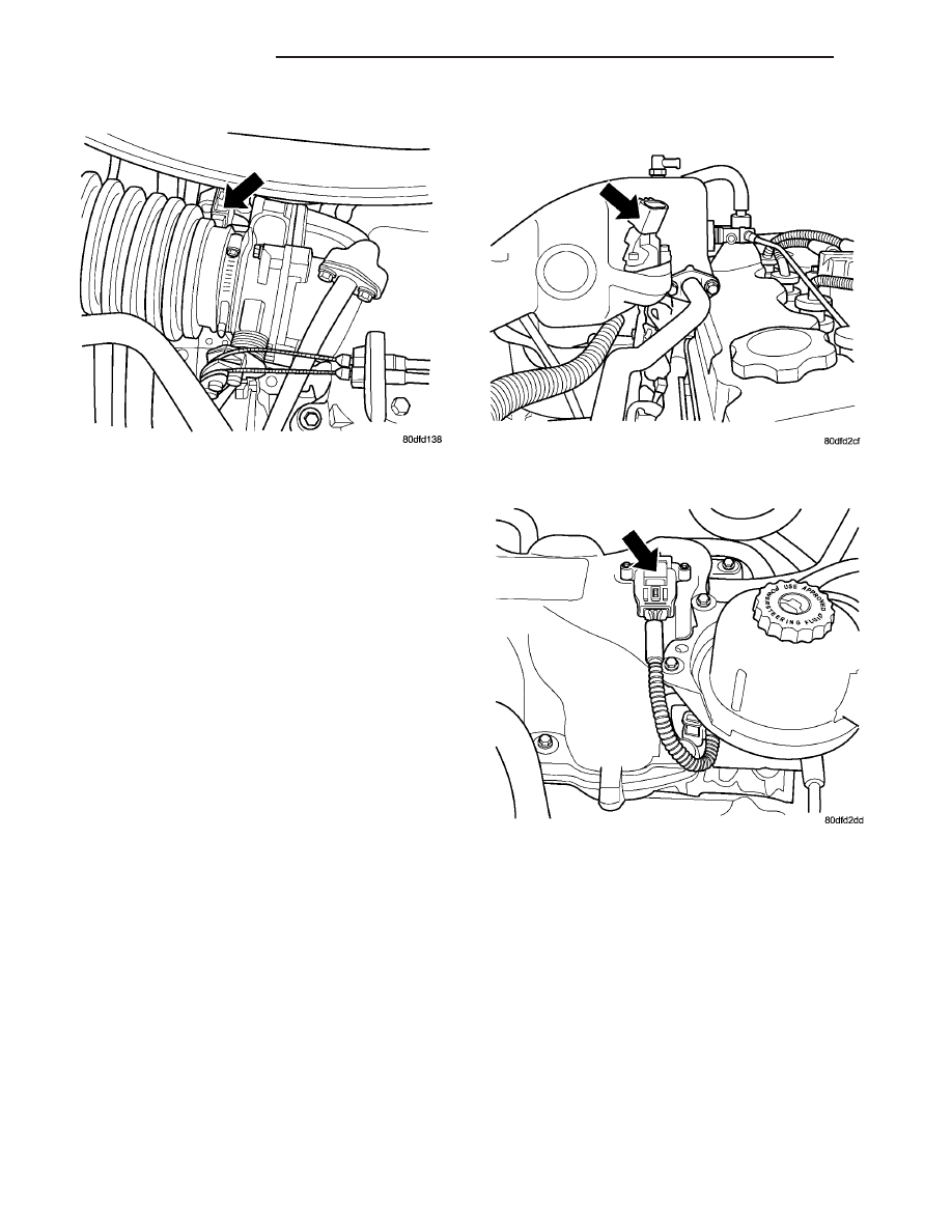
The MAP sensor (Fig. 20) or (Fig. 21) mounts to

the intake manifold. The sensor is connects electri-
cally to the PCM.

OPERATION

The MAP serves as a PCM input, using a silicon

based sensing unit, to provide data on the manifold
vacuum that draws the air/fuel mixture into the com-
bustion chamber. The PCM requires this information
to determine injector pulse width and spark advance.
When MAP equals Barometric pressure, the pulse
width will be at maximum.

Also like the cam and crank sensors, a 5 volt ref-

erence is supplied from the PCM and returns a volt-
age

signal

to

the

PCM

that

reflects

manifold

pressure. The zero pressure reading is 0.5V and full
scale is 4.5V. For a pressure swing of 0 — 15 psi the
voltage changes 4.0V. The sensor is supplied a regu-

lated 4.8 to 5.1 volts to operate the sensor. Like the
cam and crank sensors ground is provided through
the sensor return circuit.

The MAP sensor input is the number one contrib-

utor to pulse width. The most important function of
the MAP sensor is to determine barometric pressure.
The PCM needs to know if the vehicle is at sea level
or is it in Denver at 5000 feet above sea level,
because the air density changes with altitude. It will
also help to correct for varying weather conditions. If
a hurricane was coming through the pressure would
be very, very low or there could be a real fair
weather, high pressure area. This is important
because as air pressure changes the barometric pres-
sure changes. Barometric pressure and altitude have
a direct inverse correlation, as altitude goes up baro-

Fig. 19 3.3/3.8L IAT SENSOR

Fig. 20 MAP SENSOR - 2.4L

Fig. 21 MAP SENSOR - 3.3/3.8L

14 - 30

FUEL INJECTION

RS

INLET AIR TEMPERATURE SENSOR (Continued)

metric goes down. The first thing that happens as
the key is rolled on, before reaching the crank posi-
tion, the PCM powers up, comes around and looks at
the MAP voltage, and based upon the voltage it sees,
it knows the current barometric pressure relative to
altitude. Once the engine starts, the PCM looks at
the voltage again, continuously every 12 milliseconds,
and compares the current voltage to what it was at
key on. The difference between current and what it
was at key on is manifold vacuum.

During key On (engine not running) the sensor

reads (updates) barometric pressure. A normal range
can be obtained by monitoring known good sensor in
you work area.

As the altitude increases the air becomes thinner

(less oxygen). If a vehicle is started and driven to a
very different altitude than where it was at key On
the barometric pressure needs to be updated. Any
time the PCM sees Wide Open throttle, based upon
TPS angle and RPM it will update barometric pres-
sure in the MAP memory cell. With periodic updates,
the PCM can make its calculations more effectively.

The PCM uses the MAP sensor to aid in calculat-

ing the following:

• Barometric pressure

• Engine load

• Manifold pressure

• Injector pulse-width

• Spark-advance programs

• Shift-point strategies (F4AC1 transmissions

only, via the PCI bus)

• Idle speed

• Decel fuel shutoff
The PCM recognizes a decrease in manifold pres-

sure by monitoring a decrease in voltage from the
reading stored in the barometric pressure memory
cell. The MAP sensor is a linear sensor; as pressure
changes, voltage changes proportionately. The range
of voltage output from the sensor is usually between
4.6 volts at sea level to as low as 0.3 volts at 26 in. of
Hg. Barometric pressure is the pressure exerted by
the atmosphere upon an object. At sea level on a
standard day, no storm, barometric pressure is 29.92
in Hg. For every 100 feet of altitude barometric pres-
sure drops .10 in. Hg. If a storm goes through it can
either add, high pressure, or decrease, low pressure,
from what should be present for that altitude. You
should make a habit of knowing what the average
pressure and corresponding barometric pressure is
for your area.

REMOVAL

REMOVAL - 2.4L

(1) Disconnect the negative battery cable.

(2) Disconnect electrical connector and vacuum

hose from MAP sensor (Fig. 20).

(3) Remove two screws holding sensor to the

intake manifold.

REMOVAL - 3.3/3.8L

(1) Disconnect the negative battery cable.
(2) Remove vacuum hose and mounting screws

from manifold absolute pressure (MAP) sensor (Fig.
21).

(3) Disconnect electrical connector from sensor.

Remove sensor.

INSTALLATION

INSTALLATION - 2.4L

(1) Install sensor.
(2) Install two screws and tighten.
(3) Connect the electrical connector and vacuum

hose to the MAP sensor (Fig. 20).

(4) Connect the negative battery cable.

INSTALLATION - 3.3/3.8L

(1) Install sensor (Fig. 21).
(2) Install screws and tighten to PLASTIC MAN-

IFOLD 1.7 N·m (15 in. lbs.) ALUMINUM MANI-
FOLD 3.3 N·m (30 in. lbs.) 
.

(3) Connect the electrical connector to the sensor.

Install vacuum hose.

(4) Connect the negative battery cable.

O2 SENSOR

DESCRIPTION

The upstream oxygen sensor threads into the out-

let flange of the exhaust manifold (Fig. 22) or (Fig.
23).

The downstream heated oxygen sensor threads into

the outlet pipe at the rear of the catalytic convertor
(Fig. 24).

OPERATION

For SBEC vehicles a single sensor ground is used

for all 4 O2 sensors (6 Cyl.). A seperate upstream and
downstream grounds are used on the NGC vehicles
(4 Cyl.).

As vehicles accumulate mileage, the catalytic con-

vertor deteriorates. The deterioration results in a
less efficient catalyst. To monitor catalytic convertor
deterioration, the fuel injection system uses two
heated oxygen sensors. One sensor upstream of the
catalytic convertor, one downstream of the convertor.
The PCM compares the reading from the sensors to
calculate the catalytic convertor oxygen storage

RS

FUEL INJECTION

14 - 31

MAP SENSOR (Continued)

capacity and converter efficiency. Also, the PCM uses
the upstream heated oxygen sensor input when
adjusting injector pulse width.

When the catalytic converter efficiency drops below

emission standards, the PCM stores a diagnostic
trouble code and illuminates the malfunction indica-
tor lamp (MIL).

The O2 sensors produce voltages from 0 to 1 volt

(this voltage is offset by a constant 2.5 volts on NGC
vehicles), depending upon the oxygen content of the
exhaust gas. When a large amount of oxygen is
present (caused by a lean air/fuel mixture, can be
caused by misfire and exhaust leaks), the sensors
produces a low voltage. When there is a lesser
amount of oxygen present (caused by a rich air/fuel
mixture, can be caused by internal engine problems)

it produces a higher voltage. By monitoring the oxy-
gen content and converting it to electrical voltage,
the sensors act as a rich-lean switch.

The oxygen sensors are equipped with a heating

element that keeps the sensors at proper operating
temperature during all operating modes. Maintaining
correct sensor temperature at all times allows the
system to enter into closed loop operation sooner.
Also, it allows the system to remain in closed loop
operation during periods of extended idle.

In Closed Loop operation the PCM monitors the O2

sensors input (along with other inputs) and adjusts
the injector pulse width accordingly. During Open
Loop operation the PCM ignores the O2 sensor input.
The PCM adjusts injector pulse width based on pre-
programmed (fixed) values and inputs from other
sensors.

1.6L Siemens controller and SBEC controller - The

Automatic Shutdown (ASD) relay supplies battery
voltage to both the upstream and downstream heated
oxygen sensors. The oxygen sensors are equipped
with a heating element. The heating elements reduce
the time required for the sensors to reach operating
temperature. The PCM uses pulse width modulation
to control the ground side of the heater to regulate
the temperature on 4 cyl. upstream O2 heater only.

NGC Controller - Has a common ground for the

heater in the O2S. 12 volts is supplied to the heater
in the O2S by the NGC controller. Both the upstream
and downstream O2 sensors for NGC are pulse width
modulation (PWM).

UPSTREAM OXYGEN SENSOR

The input from the upstream heated oxygen sensor

tells the PCM the oxygen content of the exhaust gas.

Fig. 22 O2 SENSOR UPSTREAM 1/1 - 2.4L

Fig. 23 O2 SENSOR UPSTREAM 1/1 - 3.3/3.8L

Fig. 24 O2 SENSOR DOWNSTREAM 1/2 - 2.4/3.3/

3.8L

14 - 32

FUEL INJECTION

RS

O2 SENSOR (Continued)

Based on this input, the PCM fine tunes the air-fuel
ratio by adjusting injector pulse width.

The sensor input switches from 0 to 1 volt, depend-

ing upon the oxygen content of the exhaust gas in
the exhaust manifold (this is offset by 2.5 voltage on
NGC vehicles). When a large amount of oxygen is
present (caused by a lean air-fuel mixture), the sen-
sor produces voltage as low as 0.1 volt. When there is
a lesser amount of oxygen present (rich air-fuel mix-
ture) the sensor produces a voltage as high as 1.0
volt. By monitoring the oxygen content and convert-
ing it to electrical voltage, the sensor acts as a rich-
lean switch.

The heating element in the sensor provides heat to

the sensor ceramic element. Heating the sensor
allows the system to enter into closed loop operation
sooner. Also, it allows the system to remain in closed
loop operation during periods of extended idle.

In Closed Loop, the PCM adjusts injector pulse

width based on the upstream heated oxygen sensor
input along with other inputs. In Open Loop, the
PCM adjusts injector pulse width based on prepro-
grammed (fixed) values and inputs from other sen-
sors.

DOWNSTREAM OXYGEN SENSOR

The downstream heated oxygen sensor input is

used to detect catalytic convertor deterioration. As
the convertor deteriorates, the input from the down-
stream sensor begins to match the upstream sensor
input except for a slight time delay. By comparing
the downstream heated oxygen sensor input to the
input from the upstream sensor, the PCM calculates
catalytic convertor efficiency. Also used to establish
the upstream O2 goal voltage (switching point).

REMOVAL

REMOVAL - UPSTREAM 1/1 - 2.4L

(1) Disconnect the negative battery cable.
(2) Raise and support the vehicle.
(3) Disconnect the electrical connector (Fig. 23).
(4) Use a socket such as the Snap-On

t YA8875 or

equivalent to remove the sensor

(5) When the sensor is removed, the threads must

be cleaned with an 18 mm X 1.5 + 6E tap. If using
the original sensor, coat the threads with Loctite
771–64 anti-seize compound or equivalent.

REMOVAL - UPSTREAM 1/1 - 3.3/3.8L

(1) Remove battery, refer to the Battery section for

more information.

(2) Remove the battery tray, refer to the Battery

section for more information.

(3) Disconnect the speed control vacuum harness

from servo.

(4) Disconnect the electrical connector from servo.

(5) Remove the speed control servo and bracket

and reposition.

(6) Use a socket such as the Snap-On

t YA8875 or

equivalent to remove the sensor (Fig. 25).

(7) When the sensor is removed, the threads must

be cleaned with an 18 mm X 1.5 + 6E tap. If using
the original sensor, coat the threads with Loctite
771–64 anti-seize compound or equivalent.

REMOVAL - DOWNSTREAM 1/2 - 2.4/3.3/3.8L

(1) Disconnect the negative battery cable.
(2) Raise and support the vehicle.
(3) Disconnect the electrical connector (Fig. 26).
(4) Use a socket such as the Snap-On

t YA8875 or

equivalent to remove the sensor (Fig. 27).

(5) When the sensor is removed, the threads must

be cleaned with an 18 mm X 1.5 + 6E tap. If using
the original sensor, coat the threads with Loctite
771–64 anti-seize compound or equivalent.

INSTALLATION

INSTALLATION - UPSTREAM 1/1 - 2.4L

The engines uses two heated oxygen sensors.
(1) After removing the sensor, the exhaust mani-

fold threads must be cleaned with an 18 mm X 1.5 +
6E tap. If reusing the original sensor, coat the sensor
threads with an anti-seize compound such as Loctite
771- 64 or equivalent. New sensors have compound

Fig. 25 O2 SENSOR 1/1

RS

FUEL INJECTION

14 - 33

O2 SENSOR (Continued)


Content   ..  346  347  348  349   ..