Chrysler Town, Dodge Caravan. Manual - part 306


  Index      Chrysler     Chrysler TOWN & COUNTRY, VOYAGER, Dodge Caravan - service repair manual 2001-2007 year


Search            


Content   ..  304  305  306  307   ..


Chrysler Town, Dodge Caravan. Manual - part 306


INSTALLATION

CAUTION: If burr or scratch is present on the
crankshaft edge (chamfer), cleanup with 400 grit
sand paper to prevent seal damage during installa-
tion of new seal.

NOTE: When installing seal, no lube on seal is
needed.

(1) Place Special Tool 6926-1 Seal Guide on crank-

shaft (Fig. 57).

(2) Position seal over guide tool (Fig. 57). Guide

tool should remain on crankshaft during installation
of seal. Ensure that the lip of the seal is facing
towards the crankcase during installation.

CAUTION: If the seal is driven into the block past
flush, this may cause an oil leak.

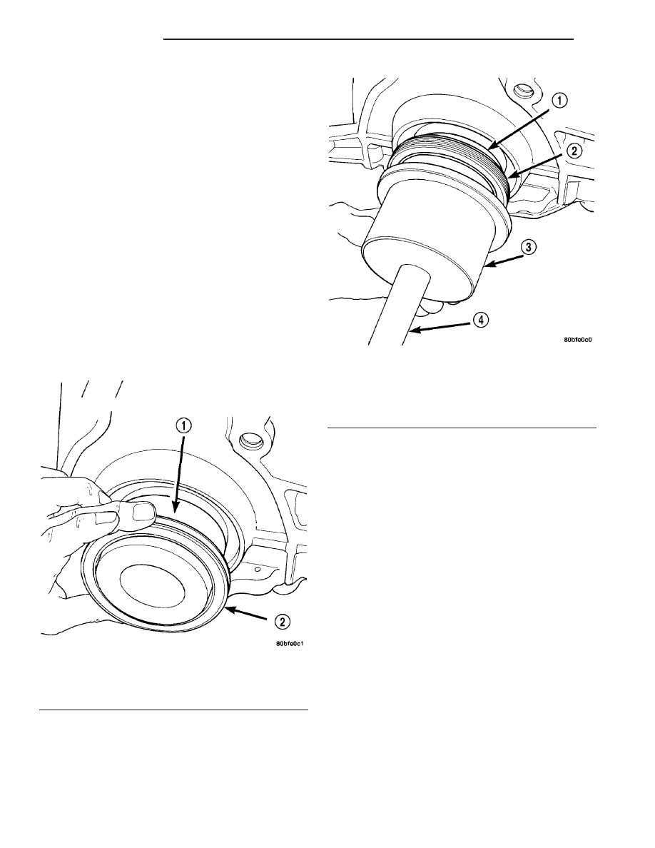
(3) Drive the seal into the block using Special Tool

6926-2 and handle C-4171 (Fig. 58) until the tool bot-
toms out against the block (Fig. 59).

(4) Install flex plate. Apply Mopar

t Lock & Seal

Adhesive to bolt threads and tighten bolts to 95 N·m
(70 ft. lbs.).

(5) Install transaxle. Refer to TRANSMISSION/

TRANSAXLE - INSTALLATION for procedure.

PISTON & CONNECTING ROD

DESCRIPTION

The pistons are made of a cast aluminum alloy.

The pistons have pressed-in pins attached to forged
powdered metal connecting rods. The pistons pin is
offset 1 mm (0.0394 in.) towards the thrust side of
the piston. The connecting rods are a cracked cap
design and are not repairable. Hex head cap screws
are used to provide alignment and durability in the
assembly. The pistons and connecting rods are ser-
viced as an assembly.

STANDARD PROCEDURE - PISTON TO
CYLINDER BORE FITTING

NOTE: Pistons and cylinder bores should be mea-
sured at normal room temperature, 21°C (70°F).

Piston and cylinder wall must be clean and dry.

Piston diameter should be measured 90 degrees to
piston pin.

Piston measurement should be taken approxi-

mately 14 mm (0.551 in.) from the bottom of the skirt
as shown in (Fig. 60)

Fig. 57 Rear Crankshaft Seal and Special Tool

6926-1

1 - SPECIAL TOOL 6926–1 PILOT
2 - SEAL

Fig. 58 Crankshaft Seal and Special Tools 6926-2 &

C-4171

1 - SPECIAL TOOL 6926–1 PILOT
2 - SEAL
3 - SPECIAL TOOL 6926–2 INSTALLER
4 - SPECIAL TOOL C-4171

9 - 42

ENGINE 2.4L

RS

CRANKSHAFT OIL SEAL - REAR (Continued)

Cylinder bores should be measured halfway down

the cylinder bore and transverse (measurement loca-
tion B) to the engine crankshaft center line shown in
(Fig. 61). Refer to for Engine Specifications (Refer to
9 - ENGINE - SPECIFICATIONS). Correct piston to
bore clearance must be established in order to assure
quiet and economical operation.

REMOVAL

(1) Remove cylinder head (Refer to 9 - ENGINE/

CYLINDER HEAD - REMOVAL).

(2) Remove oil pan (Refer to 9 - ENGINE/LUBRI-

CATION/OIL PAN - REMOVAL).

(3) Remove Balance Shaft Carrier Assembly (Refer

to 9 - ENGINE/VALVE TIMING/BALANCE SHAFT
CARRIER - REMOVAL).

(4) Remove top ridge of cylinder bores with a reli-

able ridge reamer before removing pistons from cyl-
inder block. Be sure to keep tops of pistons
covered during this operation
.

(5) Pistons have a directional stamping in the

front half of the piston facing towards the front of
engine (Fig. 62).

Fig. 59 Rear Crankshaft Seal—Installation

1 - SPECIAL TOOL 6926–2 INSTALLER

Fig. 60 Piston Measurement

1 - PISTON DIAMETER
2 - 14 mm (0.551 in.)

Fig. 61 Checking Cylinder Bore

Fig. 62 Piston Markings

1 - DIRECTIONAL ARROW WILL BE IMPRINTED IN THIS AREA

RS

ENGINE 2.4L

9 - 43

PISTON & CONNECTING ROD (Continued)

(6) Pistons and connecting rods must be removed

from top of cylinder block. Rotate crankshaft so that
each connecting rod is centered in cylinder bore.

(7) Using a permanent ink or paint marker, iden-

tify cylinder number on each connecting rod cap (Fig.
63).

CAUTION: DO NOT use a number stamp or a punch
to mark connecting rods. Damage to connecting
rod could occur.

(8) Remove connecting rod bolts and cap. Care

should be taken not to damage the fracture rod and
cap surfaces.

NOTE: Do not reuse connecting rod bolts.

CAUTION: Care must be taken not to damage the
fractured rod and cap joint surfaces, as engine
damage many occur.

(9) To protect crankshaft journal and fractured rod

surfaces, install Special Tool 8189, connecting rod
guides onto connecting rod (Fig. 64). Carefully push
each piston and rod assembly out of cylinder bore.

(10) Remove Special Tool 8189, connecting rod

guides and re-install bearing cap on the mating rod.

NOTE: Piston and rods are serviced as an assem-
bly.

(11) Repeat procedure for each piston and connect-

ing rod assembly.

(12) Remove piston rings (Refer to 9 - ENGINE/

ENGINE BLOCK/PISTON RINGS - REMOVAL).

INSTALLATION

(1) Install piston rings on piston (Refer to 9 -

ENGINE/ENGINE

BLOCK/PISTON

RINGS

-

INSTALLATION)

(2) Before installing pistons and connecting rod

assemblies into the bore, be sure that compression
ring gaps are staggered so that neither is in line with
oil ring rail gap (Fig. 65).

(3) Before installing the ring compressor, make

sure the oil ring expander ends are butted and the
rail gaps located as shown in (Fig. 65). As viewed
from top.

(4) Immerse the piston head and rings in clean

engine oil, slide the ring compressor, over the piston
(Fig. 66). Be sure position of rings does not
change during this operation.

(5) The directional stamp on the piston should face

toward the front of the engine (Fig. 62).

(6) Rotate crankshaft so that the connecting rod

journal is on the center of the cylinder bore. Lubri-
cate connecting rod journal with clean engine oil.

Fig. 63 Identify Connecting Rod to Cylinder

Fig. 64 Connecting Rod Guides—Typical

1 - SPECIAL TOOL 8189 CONNECTING ROD GUIDES

Fig. 65 Piston Ring End Gap Position

1 - GAP OF LOWER SIDE RAIL
2 - NO. 1 RING GAP
3 - GAP OF UPPER SIDE RAIL
4 - NO. 2 RING GAP AND SPACER EXPANDER GAP

9 - 44

ENGINE 2.4L

RS

PISTON & CONNECTING ROD (Continued)

(7) Install connecting rod upper bearing half into

connecting rod. Install Special Tool 8189, connecting
rod guides onto connecting rod (Fig. 64).

(8) Tap the piston down in cylinder bore, using a

hammer handle. At the same time, guide connecting
rod into position on connecting rod journal.

(9) Remove Special Tool 8189, connecting rod

guides.

NOTE: The connecting rod cap bolts should not be
reused.

(10) Before installing the NEW bolts, the threads

should be coated with clean engine oil.

(11) Install connecting rod lower bearing half into

connecting rod cap. Install connecting rod cap.

(12) Install each bolt finger tight then alternately

torque each bolt to assemble the cap properly.

(13) Tighten the connecting rod bolts using the 2

step torque-turn method. Tighten according to the
following values:

CAUTION: Do not use a torque wrench for the sec-
ond step.

1. Tighten the bolts to 27 N·m (20 ft. lbs.).
2. Tighten the connecting rod bolts an additional

1/4 TURN.

(14) Using a feeler gauge, check connecting rod

side clearance (Fig. 67). (Refer to 9 - ENGINE -
SPECIFICATIONS) for connecting rod side clearance.

(15) Install Balance Shaft Carrier Assembly (Refer

to 9 - ENGINE/VALVE TIMING/BALANCE SHAFT
CARRIER - INSTALLATION).

(16) Install oil pan (Refer to 9 - ENGINE/LUBRI-

CATION/OIL PAN - INSTALLATION).

(17) Install cylinder head (Refer to 9 - ENGINE/

CYLINDER HEAD - INSTALLATION).

CONNECTING ROD BEARINGS

STANDARD PROCEDURE

CONNECTING ROD - FITTING

(1) For measuring connecting rod bearing clear-

ance procedure and use of Plastigage (Refer to 9 -
ENGINE - STANDARD PROCEDURE). For bearing
clearance refer to Engine Specifications. (Refer to 9 -
ENGINE - SPECIFICATIONS)

NOTE: The rod bearing bolts should not be reused.

(2) Before installing the NEW bolts the threads

should be oiled with clean engine oil.

(3) Install each bolt finger tight then alternately

torque each bolt to assemble the cap properly.

(4) Tighten the connecting rod bolts using the 2

step torque-turn method. Tighten according to the
following values:

CAUTION: Do not use a torque wrench for the sec-
ond step.

1. Tighten the bolts to 27 N·m (20 ft. lbs.).
2. Tighten the connecting rod bolts an additional

1/4 TURN.

(5) Using a feeler gauge, check connecting rod side

clearance (Fig. 67). Refer to clearance specifications
(Refer to 9 - ENGINE - SPECIFICATIONS).

PISTON RINGS

STANDARD PROCEDURE

PISTON RING - FITTING

(1) Wipe cylinder bore clean. Insert ring and push

down with piston to ensure it is square in bore. The

Fig. 66 Piston—Installation

Fig. 67 Connecting Rod Side Clearance

RS

ENGINE 2.4L

9 - 45

PISTON & CONNECTING ROD (Continued)


Content   ..  304  305  306  307   ..