Chrysler Town, Dodge Caravan. Manual - part 304


  Index      Chrysler     Chrysler TOWN & COUNTRY, VOYAGER, Dodge Caravan - service repair manual 2001-2007 year


Search            


Content   ..  302  303  304  305   ..


Chrysler Town, Dodge Caravan. Manual - part 304


HYDRAULIC LASH
ADJUSTERS

DIAGNOSIS AND TESTING - HYDRAULIC LASH
ADJUSTER NOISE DIAGNOSIS

A tappet-like noise may be produced from several

items. Check the following items.

(1) Engine oil level too high or too low. This may

cause aerated oil to enter the adjusters and cause
them to be spongy.

(2) Insufficient running time after rebuilding cylin-

der head. Low speed running up to 1 hour may be
required.

(3) During this time, turn engine off and let set for

a few minutes before restarting. Repeat this several
times after engine has reached normal operating
temperature.

(4) Low oil pressure.
(5) The oil restrictor (integral to the head gasket)

in the vertical oil passage to the cylinder head is
plugged with debris.

(6) Air ingested into oil due to broken or cracked

oil pump pick up.

(7) Worn valve guides.
(8) Rocker

arm

ears

contacting

valve

spring

retainer.

(9) Rocker arm loose, adjuster stuck or at maxi-

mum extension and still leaves lash in the system.

(10) Faulty lash adjuster.
• Check lash adjusters for sponginess while

installed in cylinder head. Depress part of rocker
arm over adjuster. Normal adjusters should feel very
firm. Spongy adjusters can be bottomed out easily.

• Remove suspected lash adjusters, and replace as

necessary.

REMOVAL

NOTE: This procedure is for in-vehicle service with
camshafts installed.

(1) Remove cylinder head cover. (Refer to 9 -

ENGINE/CYLINDER

HEAD/CYLINDER

HEAD

COVER(S) - REMOVAL)

(2) Remove rocker arm. (Refer to 9 - ENGINE/

CYLINDER HEAD/ROCKER ARMS - REMOVAL)

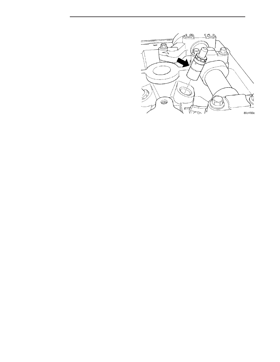
(3) Remove hydraulic lash adjuster (Fig. 37).
(4) Repeat removal procedure for each hydraulic

lash adjuster.

(5) If reusing, mark each hydraulic lash adjuster

for reassembly in original position. Lash adjusters
are serviced as an assembly.

INSTALLATION

(1) Install

hydraulic

lash

adjuster

(Fig.

37).

Ensure the lash adjusters are at least partially full of
engine oil. This is indicated by little or no plunger
travel when the lifter is depressed.

(2) Install rocker arm. (Refer to 9 - ENGINE/CYL-

INDER HEAD/ROCKER ARMS - INSTALLATION)

(3) Repeat installation procedure for each hydrau-

lic lash adjuster.

(4) Install cylinder head cover. (Refer to 9 -

ENGINE/CYLINDER

HEAD/CYLINDER

HEAD

COVER(S) - INSTALLATION)

ROCKER ARMS

REMOVAL

NOTE: This procedure is for in-vehicle service with
camshafts installed.

(1) Remove cylinder head cover. (Refer to 9 -

ENGINE/CYLINDER

HEAD/CYLINDER

HEAD

COVER(S) - REMOVAL)

(2) Remove spark plugs.
(3) Rotate engine until the camshaft lobe, on the

follower being removed, is positioned on its base cir-
cle (heel). Also, the piston should be a minimum of
6.3 mm (0.25 in) below TDC position.

CAUTION: If cam follower assemblies are to be
reused, always mark position for reassembly in
their original positions.

(4) Using Special Tools 8215A and 8436 slowly

depress valve assembly until rocker arm can be
removed (Fig. 38).

(5) Repeat removal procedure for each rocker arm.

Fig. 37 Hydraulic Lash Adjuster

9 - 34

ENGINE 2.4L

RS

INSPECTION

Inspect the rocker arm for wear or damage (Fig.

39). Replace as necessary.

INSTALLATION

(1) Lubricate rocker arm with clean engine oil.
(2) Using Special Tools 8215A and 8436 slowly

depress valve assembly until rocker arm can be
installed on the hydraulic lifter and valve stem (Fig.
38).

(3) Repeat installation procedure for each rocker

arm.

(4) Install spark plugs.

(5) Install cylinder head cover. (Refer to 9 -

ENGINE/CYLINDER

HEAD/CYLINDER

HEAD

COVER(S) - INSTALLATION)

ENGINE BLOCK

DESCRIPTION

The cast iron cylinder block is a two-piece assem-

bly, consisting of the cylinder block and bedplate (Fig.
40). The bedplate incorporates the main bearing caps
and bolts to the cylinder block. This design offers a
much stronger lower end and increased cylinder
block rigidity. The rear oil seal retainer is integral
with the block. The bedplate and block are serviced
as an assembly.

STANDARD PROCEDURE - CYLINDER BORE
HONING

(1) Used carefully, the cylinder bore resizing hone,

recommended tool C-823 or equivalent, equipped with
220 grit stones, is the best tool for this honing proce-
dure. In addition to deglazing, it will reduce taper and
out-of-round as well as removing light scuffing, scoring
or scratches. Usually a few strokes will clean up a bore
and maintain the required limits.

(2) Deglazing of the cylinder walls may be done

using a cylinder surfacing hone, recommended tool
C-3501 or equivalent, equipped with 280 grit stones,
if the cylinder bore is straight and round. 20–60
strokes depending on the bore condition, will be suf-
ficient to provide a satisfactory surface. Use a light
honing oil. Do not use engine or transmission oil,
mineral spirits or kerosene. 
Inspect cylinder walls
after each 20 strokes.

(3) Honing should be done by moving the hone up

and down fast enough to get a cross-hatch pattern.
When hone marks intersect at 40-60 degrees, the
cross hatch angle is most satisfactory for proper seat-
ing of rings (Fig. 41).

Fig. 38 Rocker Arm - Removal/Installation

1 - SPECIAL TOOL 8215A
2 - SPECIAL TOOL 8436
3 - 3/8

9

DRIVE RACHET

Fig. 39 Rocker Arm

1 - TIP
2 - LASH ADJUSTER POCKET
3 - ROLLER

Fig. 40 Cylinder Block and Bedplate

1 - CYLINDER BLOCK
2 - BEDPLATE

RS

ENGINE 2.4L

9 - 35

ROCKER ARMS (Continued)

(4)

A controlled

hone

motor

speed

between

200–300 RPM is necessary to obtain the proper cross-
hatch angle. The number of up and down strokes per
minute can be regulated to get the desired 40–60
degree angle. Faster up and down strokes increase
the cross-hatch angle.

(5) After honing, it is necessary that the block be

cleaned again to remove all traces of abrasive.

CAUTION: Ensure all abrasives are removed from
engine parts after honing. It is recommended that a
solution of soap and hot water be used with a
brush and the parts then thoroughly dried. The bore
can be considered clean when it can be wiped
clean with a white cloth and cloth remains clean.
Oil the bores after cleaning to prevent rusting.

CLEANING

Clean cylinder block thoroughly using a suitable

cleaning solvent.

INSPECTION

ENGINE BLOCK

(1) Clean cylinder block thoroughly and check all

core hole plugs for evidence of leaking.

(2) If new core plugs are to be installed, (Refer to 9

- ENGINE - STANDARD PROCEDURE - ENGINE
CORE AND OIL GALLERY PLUGS).

(3) Examine block and cylinder bores for cracks or

fractures.

(4) Check block deck surfaces for flatness. Deck

surface must be within service limit of 0.1 mm (0.004
in.).

CYLINDER BORE

NOTE: The cylinder bores should be measured at
normal room temperature, 21°C (70°F).

The cylinder walls should be checked for out-of-

round and taper with Tool C119 or equivalent (Fig.
42) (Refer to 9 - ENGINE - SPECIFICATIONS). If
the cylinder walls are badly scuffed or scored, the
cylinder block should be replaced, and new pistons
and rings fitted.

Measure the cylinder bore at three levels in direc-

tions A and B (Fig. 42). Top measurement should be
10 mm (3/8 in.) down and bottom measurement
should be 10 mm (3/8 in.) up from bottom of bore.
(Refer to 9 - ENGINE - SPECIFICATIONS).

CRANKSHAFT

STANDARD PROCEDURE - CRANKSHAFT END
PLAY

(1) Using Dial Indicator C-3339 and Mounting

Post L-4438, attach to front of engine, locating probe
perpendicular on nose of crankshaft (Fig. 43).

(2) Move crankshaft all the way to the rear of its

travel.

(3) Zero the dial indicator.

Fig. 41 Cylinder Bore Cross-Hatch Pattern

1 - CROSS-HATCH PATTERN
2 - 40°–60°

Fig. 42 Checking Cylinder Bore Size

9 - 36

ENGINE 2.4L

RS

ENGINE BLOCK (Continued)

(4) Move crankshaft all the way to the front and

read the dial indicator. Refer to Engine Specifica-
tions.

REMOVAL - CRANKSHAFT

NOTE: Crankshaft can not be removed when engine
is in vehicle.

(1) Remove engine assembly from vehicle (Refer to

9 - ENGINE - REMOVAL).

(2) Separate transaxle from engine.
(3) Remove drive plate/flex plate.
(4) Remove crankshaft rear oil seal (Refer to 9 -

ENGINE/ENGINE

BLOCK/CRANKSHAFT

OIL

SEAL - REAR - REMOVAL).

(5) Mount engine on a suitable repair stand.
(6) Drain engine oil and remove oil filter.
(7) Remove crankshaft vibration damper (Refer to

9

-

ENGINE/ENGINE

BLOCK/VIBRATION

DAMPER - REMOVAL).

(8) Remove engine mount support bracket.
(9) Remove front timing belt covers (Refer to 9 -

ENGINE/VALVE TIMING/TIMING BELT COVER(S)
- REMOVAL).

(10) Remove the timing belt (Refer to 9 - ENGINE/

VALVE TIMING/TIMING BELT AND SPROCKETS -
REMOVAL).

(11) Remove the oil pan (Refer to 9 - ENGINE/LU-

BRICATION/OIL PAN - REMOVAL).

(12) Remove oil pump pick-up tube.
(13) Remove the crankshaft sprocket and oil pump

(Refer to 9 - ENGINE/LUBRICATION/OIL PUMP -
REMOVAL).

(14) Remove balance shafts and housing assembly

(Refer to 9 - ENGINE/VALVE TIMING/BALANCE
SHAFT - REMOVAL).

(15) Remove crankshaft position sensor.

NOTE: If piston/connecting rod replacement is nec-
essary, remove cylinder head (Refer to 9 - ENGINE/
CYLINDER HEAD - REMOVAL).

(16) Using a permanent ink or paint marker, iden-

tify cylinder number on each connecting rod cap (Fig.
44).

CAUTION: DO NOT use a number stamp or a punch
to mark connecting rods. Damage to connecting
rod could occur.

(17) Remove all connecting rod bolts and caps.

Care should be taken not to damage the fracture rod
and cap surfaces.

NOTE: Do not reuse connecting rod bolts.

(18) Remove all bedplate bolts from the engine

block (Fig. 45).

(19) Using a mallet gently tap the bedplate loose

from the engine block dowel pins.

CAUTION: Do not pry up on one side of the bed-
plate. Damage may occur to cylinder block to bed-
plate alignment and thrust bearing.

(20) Bedplate should be removed evenly from the

cylinder block dowel pins to prevent damage to the
dowel pins and thrust bearing.

CAUTION: Use extreme care when handling crank-
shaft. Tone wheel damage can occur if crankshaft is
mis-handled.

(21) Lift out crankshaft from cylinder block. Do

not damage the main bearings or journals when
removing the crankshaft.

INSPECTION

For crankshaft specifications (Refer to 9 - ENGINE

- SPECIFICATIONS).

Fig. 43 CHECKING CRANKSHAFT END PLAY

Fig. 44 Identify Connecting Rod to Cylinder

RS

ENGINE 2.4L

9 - 37

CRANKSHAFT (Continued)


Content   ..  302  303  304  305   ..