Chrysler Town, Dodge Caravan. Manual - part 302


  Index      Chrysler     Chrysler TOWN & COUNTRY, VOYAGER, Dodge Caravan - service repair manual 2001-2007 year


Search            


Content   ..  300  301  302  303   ..


Chrysler Town, Dodge Caravan. Manual - part 302


(15) Remove cylinder head cover. (Refer to 9 -

ENGINE/CYLINDER

HEAD/CYLINDER

HEAD

COVER(S) - REMOVAL)

(16) Remove camshafts (Refer to 9 - ENGINE/

CYLINDER HEAD/CAMSHAFT(S) - REMOVAL).

NOTE: Identify rocker arm position to ensure cor-
rect re-installation in original position, if reused.

(17) Remove rocker arms. (Refer to 9 - ENGINE/

CYLINDER HEAD/ROCKER ARMS - REMOVAL)

(18) Remove cylinder head bolts in REVERSE

sequence of tightening (Fig. 19).

(19) Remove cylinder head from engine block.
(20) Inspect and clean cylinder head. (Refer to 9 -

ENGINE/CYLINDER HEAD - INSPECTION) (Refer
to 9 - ENGINE/CYLINDER HEAD - CLEANING)

CLEANING

To ensure engine gasket sealing, proper surface

preparation must be performed, especially with the
use of aluminum engine components and multi-layer
steel cylinder head gaskets.

NOTE: Multi-Layer Steel (MLS) head gaskets require
a scratch free sealing surface.

Remove all gasket material from cylinder head and

block (Refer to 9 - ENGINE - STANDARD PROCE-
DURE). Be careful not to gouge or scratch the alumi-
num head sealing surface.

Clean all engine oil passages.

INSPECTION

(1)

Cylinder head must be flat within 0.1 mm

(0.004 in.) (Fig. 14).

(2)

Inspect camshaft bearing journals for scoring.

(3) Remove carbon and varnish deposits from

inside of valve guides with a reliable guide cleaner.

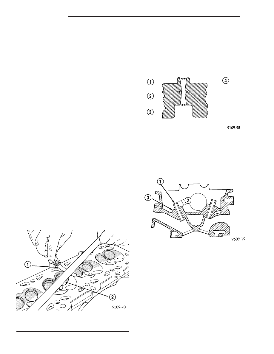
(4) Using a small hole gauge and a micrometer,

measure valve guides in 3 places top, middle and bot-
tom (Fig. 15). (Refer to 9 - ENGINE - SPECIFICA-
TIONS) Replace guides if they are not within
specification.

(5) Check valve guide height (Fig. 16).

INSTALLATION - CYLINDER HEAD

NOTE: The Cylinder head bolts should be examined
BEFORE reuse. If the threads are necked down, the
bolts must be replaced (Fig. 17).

Necking can be checked by holding a scale or

straight edge against the threads. If all the threads
do not contact the scale, the bolt should be replaced.

(1) Before installing the bolts, the threads should

be coated with engine oil.

Fig. 14 Checking Cylinder Head Flatness

1 - FEELER GAUGE
2 - STRAIGHT EDGE

Fig. 15 Checking Wear on Valve Guide—Typical

1 - TOP
2 - MIDDLE
3 - BOTTOM
4 - CUT AWAY VIEW OF VALVE GUIDE MEASUREMENT
LOCATIONS

Fig. 16 Valve Guide Height

1 - VALVE GUIDE
2 - 13.25 - 13.75 MM (0.521 - 0.541 IN.)
3 - SPRING SEAT

9 - 26

ENGINE 2.4L

RS

CYLINDER HEAD (Continued)

(2) Position cylinder head gasket on engine block

(Fig. 18).

(3) Install cylinder head on engine block.
(4) Tighten the cylinder head bolts in the sequence

shown in (Fig. 19). Using the 4 step torque turn
method, tighten according to the following values:

• First All to 34 N·m (25 ft. lbs.)

• Second All to 68 N·m (50 ft. lbs.)

• Third All to 68 N·m (50 ft. lbs.)

CAUTION: Do not use a torque wrench for the fol-
lowing step.

• Fourth Turn an additional 1/4 Turn,
(5) Install rocker arms. (Refer to 9 - ENGINE/

CYLINDER HEAD/ROCKER ARMS - INSTALLA-
TION)

(6) Install camshafts. (Refer to 9 - ENGINE/CYL-

INDER HEAD/CAMSHAFT(S) - INSTALLATION).

(7) Install cylinder head cover. (Refer to 9 -

ENGINE/CYLINDER

HEAD/CYLINDER

HEAD

COVER(S) - INSTALLATION)

(8) Install timing belt rear cover and timing belt

idler pulley. (Refer to 9 - ENGINE/VALVE TIMING/
TIMING BELT / CHAIN COVER(S) - INSTALLA-
TION)

(9)

Install timing belt and camshaft sprockets.

(Refer to 9 - ENGINE/VALVE TIMING/TIMING
BELT/CHAIN AND SPROCKETS - INSTALLATION)

(10) Connect cam sensor and fuel injectors wiring

connectors.

(11) Install ignition coil and wires. Connect igni-

tion coil wiring connector.

(12) Install power steering pump reservoir and

line support bracket to cylinder head.

(13) Raise vehicle and install the exhaust pipe to

the manifold.

(14) Install accessory drive belts. (Refer to 7 -

COOLING/ACCESSORY

DRIVE/DRIVE

BELTS

-

INSTALLATION)

(15) Install heater tube support bracket to cylinder

head.

(16) Connect radiator upper and heater hoses to

intake manifold water outlet connections.

(17) Install upper intake manifold. (Refer to 9 -

ENGINE/MANIFOLDS/INTAKE

MANIFOLD

-

INSTALLATION)

(18) Using new gaskets, install EGR tube and

tighten fasteners to 11 N·m (95 in. lbs.).

(19) Install air inlet tube and housing.
(20) Connect all vacuum lines, electrical wiring,

ground straps and fuel line.

(21) Fill cooling system. (Refer to 7 - COOLING -

STANDARD PROCEDURE)

(22) Connect battery negative cable.

CAMSHAFT OIL SEAL(S)

REMOVAL

(1) Remove timing belt (Refer to 9 - ENGINE/

VALVE TIMING/TIMING BELT AND SPROCKETS -
REMOVAL).

Fig. 17 Checking Bolts for Stretching (Necking)

1 - STRETCHED BOLT
2 - THREADS ARE NOT STRAIGHT ON LINE
3 - THREADS ARE STRAIGHT ON LINE
4 - UNSTRETCHED BOLT

Fig. 18 Cylinder Head Gasket Positioning

1 - PART NUMBER FACES UP
2 - NO. 1 CYLINDER

Fig. 19 Cylinder Head Tightening Sequence

RS

ENGINE 2.4L

9 - 27

CYLINDER HEAD (Continued)

(2) Hold each camshaft sprocket with Special Tool

6847 while removing center bolt (Fig. 20).

(3) Remove camshaft sprockets.
(4) Remove rear timing belt cover (Refer to 9 -

ENGINE/VALVE TIMING/TIMING BELT COVER(S)
- REMOVAL).

(5) Remove

camshaft

seal

using

Special

Tool

C-4679A (Fig. 21).

CAUTION: Do not nick shaft seal surface or seal
bore.

INSTALLATION

(1) Shaft seal surface must be free of varnish, dirt

or nicks. Polish with 400 grit paper if necessary.

(2) Install camshaft seals into cylinder head using

Special Tool MD-998306 until flush with head (Fig.
22).

(3) Install timing belt rear cover (Refer to 9 -

ENGINE/VALVE TIMING/TIMING BELT COVER(S)
- INSTALLATION).

(4) Install camshaft sprockets. Hold each sprocket

with Special Tool 6847 and tighten center bolt to 101
N·m (75 ft. lbs.) (Fig. 20).

(5) Install timing belt and front covers (Refer to 9 -

ENGINE/VALVE

TIMING/TIMING

BELT

AND

SPROCKETS

-

INSTALLATION)

(Refer

to

9

-

ENGINE/VALVE TIMING/TIMING BELT COVER(S)
- INSTALLATION).

CAMSHAFT(S)

DESCRIPTION

Both camshafts have six bearing journal surfaces

and two cam lobes per cylinder (Fig. 23). Flanges at
the rear journals control camshaft end play. Provision
for a cam position sensor is located on the intake
camshaft on the rear of the cylinder head. A hydro-
dynamic oil seal is used for oil control at the front of
the camshaft.

OPERATION

The camshaft is driven by the crankshaft via drive

sprockets and belt. The camshaft has precisely
machined lobes to provide accurate valve timing and
duration.

Fig. 20 Camshaft Sprocket - Removal/Installation

1 - SPECIAL TOOL 6847

Fig. 21 Camshaft Oil Seal - Removal With C-4679A

1 - SPECIAL TOOL C-4679

Fig. 22 Camshaft Seal - Installation

1 - SPECIAL TOOL MD-998306

9 - 28

ENGINE 2.4L

RS

CAMSHAFT OIL SEAL(S) (Continued)

STANDARD PROCEDURE - MEASURING
CAMSHAFT END PLAY

(1) Oil camshaft journals and install camshaft

WITHOUT rocker arms. Install rear cam caps and
tighten screws to specified torque.

(2) Using a suitable tool, move camshaft as far

rearward as it will go.

(3) Zero dial indicator (Fig. 24).
(4) Move camshaft as far forward as it will go.
(5) Record reading on dial indicator. For end play

specification, (Refer to 9 - ENGINE - SPECIFICA-
TIONS).

(6) If end play is excessive, check cylinder head

and camshaft for wear; replace as necessary.

REMOVAL

(1) Remove cylinder head cover (Refer to 9 -

ENGINE/CYLINDER

HEAD/CYLINDER

HEAD

COVER - REMOVAL).

(2) Remove camshaft position sensor and camshaft

target magnet (Refer to 8 - ELECTRICAL/IGNITION
CONTROL/CAMSHAFT

POSITION

SENSOR

-

REMOVAL).

(3) Remove timing belt (Refer to 9 - ENGINE/

VALVE TIMING/TIMING BELT AND SPROCKETS -
REMOVAL).

(4) Remove camshaft sprockets and timing belt

rear cover (Refer to 9 - ENGINE/VALVE TIMING/
TIMING BELT COVER(S) - REMOVAL).

(5) Bearing

caps

are

identified

for

location.

Remove the outside bearing caps first (Fig. 25).

(6)

Loosen the camshaft bearing cap attaching

fasteners in sequence shown (Fig. 26) one camshaft
at a time.

CAUTION: Camshafts are not interchangeable. The
intake cam number 6 thrust bearing face spacing is
wider.

(7) Identify the camshafts before removing from

the head. The camshafts are not interchangeable.

(8) Remove camshafts from cylinder head.

NOTE: If removing rocker arms, identify for reinstal-
lation in the original position.

CLEANING

Clean camshaft with a suitable solvent.

Fig. 23 Camshafts

1 - CAMSHAFT BEARING CAPS
2 - PLUG
3 - CAMSHAFT
4 - CYLINDER HEAD
5 - CAMSHAFT OIL SEAL

Fig. 24 Camshaft End Play - Typical

Fig. 25 Camshaft Bearing Cap Identification

RS

ENGINE 2.4L

9 - 29

CAMSHAFT(S) (Continued)


Content   ..  300  301  302  303   ..