Chrysler Town, Dodge Caravan. Manual - part 142


  Index      Chrysler     Chrysler TOWN & COUNTRY, VOYAGER, Dodge Caravan - service repair manual 2001-2007 year


Search            


Content   ..  140  141  142  143   ..


Chrysler Town, Dodge Caravan. Manual - part 142


(12) Disconnect the reservoir from the body mount

by raising the reservoir upward slightly and then
down so that the reservoir filler neck and front
washer hose pull through the opening in the front
fender side shield.

(13) Remove pump from reservoir by pulling pump

upper retention tab away from reservoir cavity and
then lifting pump up from mounting grommet. Do
not damage reservoir/pump sealing surface or punc-
ture reservoir during removal.

(14) Remove pump grommet and discard.

INSTALLATION

(1) Use new grommet when installing a new pump

assembly.

(2) Assure pump upper retention tab is pressed

into reservoir slot and that pump is rotated flat
against the reservoir and that pump connector is fac-
ing up in the fully seated position. Assure the pump
is aligned to and fully seated in the reservoir cavity.

(3) Push filler neck and front washer hose through

the opening in the front fender side shield. Connect
the reservoir to the body mount by lowering the res-
ervoir down.

(4) Install the two reservoir mounting screws.

Torque screws to 8.5 - 11.3 N·m (75 - 100 in. lbs.).

(5) Connect the electrical body harness connectors

to the washer pump motors and the fluid level sen-
sor. Slide the red lock on the connector to the closed
or locked position.

(6) Assure that washer hose is properly routed to

prevent pinching and possible inoperative washers.

(7) Connect the left right front wheelhouse splash

shield and move aside (Refer to 23 - BODY/EXTERI-
OR/WHEELHOUSE SPLASH SHIELD - INSTALLA-
TION).

(8) Install the right front wheel and tire assembly

(Refer to 22 - TIRES/WHEELS - INSTALLATION).

(9) lower vehicle from hoist or jack stands.
(10) Install the filler tube screw. Torque screw to

8.5 - 11.3 N·m (75 - 100 in. lbs.).

(11) Connect the washer hose to the hose clip

located on the front fender side shield.

(12) Connect the washer hose at the in-line con-

nector forward of the cowl grille.

(13) Install the engine fresh air housing inside the

engine compartment (Refer to 9 - ENGINE/AIR
INTAKE

SYSTEM/AIR

CLEANER

HOUSING

-

INSTALLATION).

(14) Connect the battery negative cable.
(15) Verify system operation.

REAR WIPER ARM

REMOVAL

(1) Remove arm nut cap.
(2) Remove wiper arm nut.
(3) Pull wiper from pivot by rocking back and

forth.

INSTALLATION

(1) Verify that wipers are in parked position.
(2) Position arm on pivot.
(3) Install wiper arm nut and torque to 20 N·m

(175 in. lbs.).

REAR WIPER MOTOR

REMOVAL

(1) Disconnect and isolate the battery negative

cable.

(2) Remove rear wiper arm. (Refer to 8 - ELEC-

TRICAL/WIPERS/WASHERS/REAR WIPER ARM -
REMOVAL) in this section.

(3) Open liftgate.
(4) Remove liftgate trim panel. (Refer to 23 -

BODY/DECKLID/HATCH/LIFTGATE/TAILGATE/
TRIM PANEL - REMOVAL).

(5) Disconnect wire connector from rear wiper

motor.

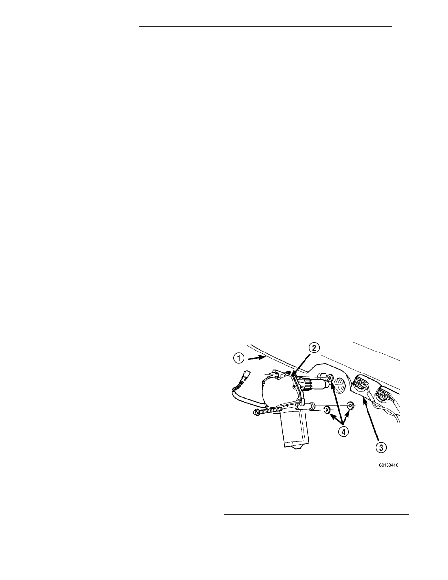
(6) Remove screws holding rear wiper motor to lift-

gate (Fig. 4).

(7) Remove wiper motor from liftgate.

Fig. 4 REAR WINDOW WIPER MOTOR

1 - REAR WINDOW
2 - REAR WIPER MOTOR
3 - CHMSL
4 - WELL NUTS

8R - 14

WIPERS/WASHERS

RS

REAR WASHER PUMP MOTOR (Continued)

INSTALLATION

(1) Position the wiper motor in the liftgate.
(2) Install the retaining screws.
(3) Connect the wire harness connector.
(4) Install the liftgate trim panel. (Refer to 23 -

BODY/DECKLID/HATCH/LIFTGATE/TAILGATE/
TRIM PANEL - INSTALLATION).

(5) Connect wire connector to rear wiper motor.
(6) Install the screws holding rear wiper motor to

liftgate (Fig. 4).

(7) Install the wiper motor to the liftgate (Fig. 4).
(8) Close the liftgate.
(9) Install the wiper arm. (Refer to 8 - ELECTRI-

CAL/WIPERS/WASHERS/REAR

WIPER

ARM

-

INSTALLATION) in this section.

(10) Connect the battery negative cable.

REAR WIPER/WASHER
SWITCH

DESCRIPTION

The

rear

window

wiper/washer

switches

are

located on the center bezel with the hazard and
heated seat switches (Fig. 5). They are not service-
able separately from the hazard and heated seat
switches. If defective, the entire switch assembly
must be replaced.

OPERATION

Refer to the vehicle Owner’s Manual for operating

instructions for the rear window wiper and washer.

WASHER FLUID LEVEL
SWITCH

REMOVAL

(1) Disconnect and isolate the battery negative

cable.

(2) Remove the engine fresh air housing inside the

engine compartment (Refer to 9 - ENGINE/AIR
INTAKE

SYSTEM/AIR

CLEANER

HOUSING

-

REMOVAL).

(3) Disconnect the washer hose at the in-line con-

nector forward of the cowl grille so that the in-line
connector remains with the washer hose from the
fresh air plenum.

(4) Disconnect the washer hose from the hose clip

located on the front fender side shield.

(5) Remove the filler tube screw.
(6) Hoist and support vehicle on hoist or jack

stands.

(7) Remove the right front wheel and tire assembly

(Refer to 22 - TIRES/WHEELS - REMOVAL).

(8) Disconnect the left right front wheelhouse

splash shield and move aside (Refer to 23 - BODY/
EXTERIOR/WHEELHOUSE

SPLASH

SHIELD

-

REMOVAL).

(9) Drain washer fluid from the reservoir and into

a suitable clean container. This can be done by dis-
connecting the windshield washer hose from the
front (outboard) washer pump and allowing the
washer fluid to drain into a container through a tem-
porary jumper hose connected to the front washer
pump.

(10) Disconnect the electrical body harness connec-

tors to the washer pump motors and the fluid level
sensor. Slide the red lock on the connector to the
release position, then, depress the black tab and pull
the connector off the pump or sensor.

(11) Remove the two reservoir mounting screws.
(12) Disconnect the reservoir from the body mount

by raising the reservoir upward slightly and then
down so that the reservoir filler neck and front
washer hose pull through the opening in the front
fender side shield.

(13) Remove the sensor from reservoir by using a

side foot to gently pry the sensor from the body of
the reservoir. Do not damage the reservoir/sensor
sealing surface or puncture reservoir during removal.

CAUTION: To avoid damage to the sensor, assure
the reservoir is in an upright position before remov-
ing the sensor from the reservoir. Do not rotate the
sensor during removal.

Fig. 5 HVAC CONTROL PANEL

1 - TRIM BEZEL
2 - IN CAR TEMPERATURE SENSOR
3 - A/C REQUEST SWITCH
4 - REAR WINDOW DEFOGGER/HEATED MIRRORS SWITCH
COMBO
5 - FRONT WINDOW DEFROSTER MODE SELECTOR

RS

WIPERS/WASHERS

8R - 15

REAR WIPER MOTOR (Continued)

INSTALLATION

(1) Use a new grommet when installing a new sen-

sor assembly.

(2) Assure that the flat of the sensor is aligned

under the ridge of the reservoir and that the sensor
connector is facing down in the fully seated position.
This will allow for proper operation of the sensor
float switch.

(3) Push filler neck and front washer hose through

the opening in the front fender side shield. Connect
the reservoir to the body mount by lowering the res-
ervoir down.

(4) Install the two reservoir mounting screws.

Torque screws to 8.5 - 11.3 N·m (75 - 100 in. lbs.).

(5) Connect the electrical body harness connectors

to the washer pump motors and the fluid level sen-
sor. Slide the red lock on the connector to the closed
or locked position.

(6) Assure that washer hose is properly routed to

prevent pinching and possible inoperative washers.

(7) Connect the left right front wheelhouse splash

shield and move aside (Refer to 23 - BODY/EXTERI-
OR/WHEELHOUSE SPLASH SHIELD - INSTALLA-
TION).

(8) Install the right front wheel and tire assembly

(Refer to 22 - TIRES/WHEELS - INSTALLATION).

(9) lower vehicle from hoist or jack stands.
(10) Install the filler tube screw. Torque screw to

8.5 - 11.3 N·m (75 - 100 in. lbs.).

(11) Connect the washer hose to the hose clip

located on the front fender side shield.

(12) Connect the washer hose at the in-line con-

nector forward of the cowl grille.

(13) Install the engine fresh air housing inside the

engine compartment (Refer to 9 - ENGINE/AIR
INTAKE

SYSTEM/AIR

CLEANER

HOUSING

-

INSTALLATION).

(14) Connect the battery negative cable.
(15) Verify system operation.

WASHER HOSES

REMOVAL

(1) Remove washer reservoir from vehicle (Refer to

8

-

ELECTRICAL/WIPERS/WASHERS/WASHER

RESERVOIR - REMOVAL).

(2) Disconnect washer hose front the reservoir cav-

ity.

(3) Disconnect the washer hose from the reservoir

pump.

(4) Remove parts as necessary to replace washer

hose (engine compartment, interior components, etc.).

INSTALLATION

(1) Install parts as necessary to after replacing

washer hose (engine compartment, interior compo-
nents, etc.).

(2) Connect the washer hose to the reservoir

pump.

(3) Connect washer hose to the reservoir cavity.
(4) Install the washer reservoir into vehicle (Refer

to 8 - ELECTRICAL/WIPERS/WASHERS/WASHER
RESERVOIR - INSTALLATION).

WASHER RESERVOIR

REMOVAL

(1) Disconnect and isolate the battery negative

cable.

(2) Remove the engine fresh air housing inside the

engine compartment (Refer to 9 - ENGINE/AIR
INTAKE

SYSTEM/AIR

CLEANER

HOUSING

-

REMOVAL).

(3) Disconnect the washer hose at the in-line con-

nector forward of the cowl grille so that the in-line
connector remains with the washer hose from the
fresh air plenum.

(4) Disconnect the washer hose from the hose clip

located on the front fender side shield.

(5) Remove the filler tube screw.
(6) Hoist and support vehicle on hoist or jack

stands.

(7) Remove the right front wheel and tire assembly

(Refer to 22 - TIRES/WHEELS - REMOVAL).

(8) Disconnect the left right front wheelhouse

splash shield and move aside (Refer to 23 - BODY/
EXTERIOR/WHEELHOUSE

SPLASH

SHIELD

-

REMOVAL).

(9) Drain washer fluid from the reservoir and into

a suitable clean container. This can be done by dis-
connecting the windshield washer hose from the
front (outboard) washer pump and allowing the
washer fluid to drain into a container through a tem-
porary jumper hose connected to the front washer
pump.

(10) Disconnect the electrical body harness connec-

tors to the washer pump motors and the fluid level
sensor. Slide the red lock on the connector to the
release position, then, depress the black tab and pull
the connector off the pump or sensor.

(11) Remove the two reservoir mounting screws.
(12) Disconnect the reservoir from the body mount

by raising the reservoir upward slightly and then
down so that the reservoir filler neck and front
washer hose pull through the opening in the front
fender side shield.

8R - 16

WIPERS/WASHERS

RS

WASHER FLUID LEVEL SWITCH (Continued)

INSTALLATION

(1) Push filler neck and front washer hose through

the opening in the front fender side shield. Connect
the reservoir to the body mount by lowering the res-
ervoir down.

(2) Install the two reservoir mounting screws.

Torque screws to 8.5 - 11.3 N·m (75 - 100 in. lbs.).

(3) Connect the electrical body harness connectors

to the washer pump motors and the fluid level sen-
sor. Slide the red lock on the connector to the closed
or locked position.

(4) Assure that washer is properly routed to pre-

vent pinching and possible inoperative washers.

(5) Connect the left right front wheelhouse splash

shield and move aside (Refer to 23 - BODY/EXTERIOR/
WHEELHOUSE SPLASH SHIELD - INSTALLATION).

(6) Install the right front wheel and tire assembly

(Refer to 22 - TIRES/WHEELS - INSTALLATION).

(7) lower vehicle from hoist or jack stands.
(8) Install the filler tube screw. Torque screw to 8.5

- 11.3 N·m (75 - 100 in. lbs.).

(9) Connect the washer hose to the hose clip

located on the front fender side shield.

(10) Connect the washer hose at the in-line con-

nector forward of the cowl grille.

(11) Install the engine fresh air housing inside the

engine compartment (Refer to 9 - ENGINE/AIR
INTAKE

SYSTEM/AIR

CLEANER

HOUSING

-

INSTALLATION).

(12) Connect the battery negative cable.
(13) Verify system operation.

WIPER BLADES

REMOVAL

(1) Lift the wiper arm away from the glass.
(2) Disengage the release tab holding the wiper

blade to the wiper arm and remove the wiper blade
from the wiper arm (Fig. 6) and (Fig. 7).

CLEANING

Wiper blades exposed to the weather for a long

period of time tend to lose their wiping effectiveness.
Periodic cleaning of the wiper blade is recommended to
remove the accumulation of salt and road grime. The
wiper blades, arms and windshield should be cleaned
with a sponge or cloth and a mild detergent or non-
abrasive cleaner. If the wiper blades continue to streak
or smear, they should be replaced. The wiper blade
should run smoothly across the windshield in both
directions. The wiper blade should slightly roll over
center when the blade reverses direction. A wiper
blade insert that has lost flexibility or a wiper arm
that has lost spring tension, will cause the blade to
skip or chatter across the windshield. If the wiper
blades are new and the wiper arm spring tension is
OK and a chattering sound is emitted from the wip-
er(s), the wiper blade is not rolling over center. If this
condition exists, (refer to 8 - ELECTRICAL/WIPERS/
WASHERS/WIPER ARMS - ADJUSTMENTS).

INSTALLATION

(1) Position the blade onto the arm.
(2) Engage the blade to the retainer by pulling up

on the blade until the tabs snap into position (Fig. 6).

WIPER LINKAGE

REMOVAL

(1) Remove the front windshield wiper unit from

vehicle (Refer to 8 - ELECTRICAL/WIPERS/WASH-
ERS/WIPER MODULE - REMOVAL).

(2) Place the wiper unit on a suitable work surface.
(3) Remove nuts holding the cowl cover brackets to

the wiper unit.

(4) Remove cowl cover brackets from the wiper unit.
(5) Remove nuts holding linkage to the wiper unit.
(6) Remove the wiper linkage from the wiper unit.
(7) Disconnect the wire connectors from back of

the wiper motor.

Fig. 6 WINDSHIELD WIPER BLADE

1 - RELEASE TAB

Fig. 7 REAR WIPER

1 - WIPER ARM
2 - BLADE LATCH

RS

WIPERS/WASHERS

8R - 17

WASHER RESERVOIR (Continued)


Content   ..  140  141  142  143   ..