Chrysler Town, Dodge Caravan. Manual - part 143


  Index      Chrysler     Chrysler TOWN & COUNTRY, VOYAGER, Dodge Caravan - service repair manual 2001-2007 year


Search            


Content   ..  141  142  143  144   ..


Chrysler Town, Dodge Caravan. Manual - part 143


INSTALLATION

(1) Connect the wire harness connector.
(2) Install the linkage on the wiper unit.
(3) Install the nut holding the linkage to the wiper

unit.

(4) Install the cowl cover brackets to the wiper nut.
(5) Install the front wiper unit (Refer to 8 - ELEC-

TRICAL/WIPERS/WASHERS/WIPER

MODULE

-

INSTALLATION).

(6) Install the cowl cover.
(7) Install the wiper arms and blades.

WIPER MODULE

REMOVAL

(1) Release the hood latch and open hood.
(2) Disconnect and isolate the battery negative

cable.

(3) Remove the wiper arms.
(4) Remove the cowl cover (Refer to 23 - BODY/

EXTERIOR/COWL GRILLE - REMOVAL).

(5) Disconnect the positive lock on the wiper mod-

ule wire connector (Fig. 8).

(6) Disconnect the wiper module wire connector

from the engine compartment wire harness.

(7) Disconnect the windshield washer hose from

coupling outside the module.

(8) Disconnect the drain tubes from nipples on bot-

tom of the wiper module.

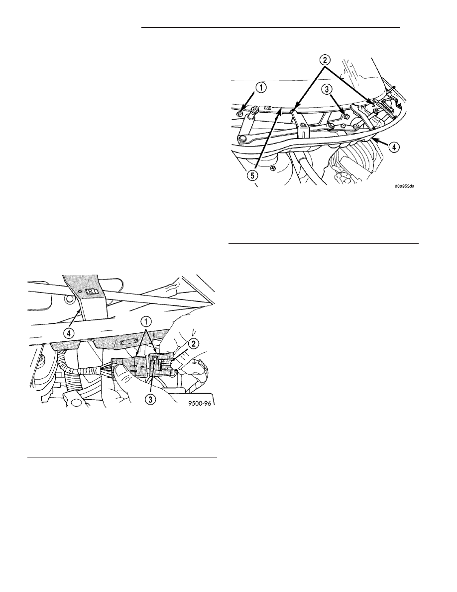
(9) Remove nuts holding wiper module to lower

windshield fence.

(10) Remove bolts holding the wiper module to the

dash panel (Fig. 9).

(11) Lift wiper module from weld-studs on lower

windshield fence.

CAUTION: Do not allow wiper module to rest on
brake master cylinder reservoir, damage to brake
system can result.

(12) Remove wiper module.

INSTALLATION

(1) Position the wiper module into the cowl.
(2) Install the bolts that secure the wiper module

to the dash (Fig. 9).

(3) Install the nuts that retain the wiper module.
(4) Connect the drain tubes to the nipples on the

wiper module.

(5) Connect the windshield washer tube.
(6) Connect the wire harness connector to the

wiper module (Fig. 9).

(7) Connect the positive lock on the wiper module

wire connector (Fig. 8).

CAUTION: Do not allow wiper module to rest on
brake master cylinder reservoir, damage to brake
system can result.

(8) Install the cowl cover (Refer to 23 - BODY/EX-

TERIOR/COWL GRILLE - INSTALLATION).

(9) Install the wiper arms and blades.
(10) Connect the battery negative cable.
(11) Close the hood.

Fig. 8 WIPER MODULE WIRE CONNECTOR

1 - WIPER SYSTEM WIRE CONNECTOR
2 - LOCK TAB
3 - POSITIVE LOCK
4 - WIPER MODULE

Fig. 9 WIPER MODULE

1 - BOLT
2 - NUTS
3 - BOLT
4 - WIPER MODULE
5 - WINDSHIELD

8R - 18

WIPERS/WASHERS

RS

WIPER LINKAGE (Continued)

WIRING

TABLE OF CONTENTS

page

page

WIRING DIAGRAM INFORMATION. . . . . . . 8W-01-1
COMPONENT INDEX . . . . . . . . . . . . . . . . . . 8W-02-1
POWER DISTRIBUTION . . . . . . . . . . . . . . . 8W-10-1
GROUND DISTRIBUTION . . . . . . . . . . . . . . 8W-15-1
BUS COMMUNICATIONS . . . . . . . . . . . . . . 8W-18-1
CHARGING SYSTEM . . . . . . . . . . . . . . . . . . 8W-20-1
STARTING SYSTEM . . . . . . . . . . . . . . . . . . 8W-21-1
FUEL/IGNITION SYSTEM . . . . . . . . . . . . . . 8W-30-1
TRANSMISSION CONTROL SYSTEM . . . . . 8W-31-1
VEHICLE SPEED CONTROL . . . . . . . . . . . . 8W-33-1
ANTILOCK BRAKES. . . . . . . . . . . . . . . . . . . 8W-35-1
VEHICLE THEFT SECURITY SYSTEM . . . . . 8W-39-1
INSTRUMENT CLUSTER . . . . . . . . . . . . . . . 8W-40-1
HORN/CIGAR LIGHTER/POWER OUTLET . . 8W-41-1
AIR CONDITIONING-HEATER . . . . . . . . . . . 8W-42-1
AIRBAG SYSTEM . . . . . . . . . . . . . . . . . . . . 8W-43-1
INTERIOR LIGHTING. . . . . . . . . . . . . . . . . . 8W-44-1
BODY CONTROL MODULE . . . . . . . . . . . . . 8W-45-1
MESSAGE CENTER . . . . . . . . . . . . . . . . . . . 8W-46-1

AUDIO SYSTEM . . . . . . . . . . . . . . . . . . . . . 8W-47-1
REAR WINDOW DEFOGGER. . . . . . . . . . . . 8W-48-1
OVERHEAD CONSOLE. . . . . . . . . . . . . . . . . 8W-49-1
FRONT LIGHTING . . . . . . . . . . . . . . . . . . . . 8W-50-1
REAR LIGHTING . . . . . . . . . . . . . . . . . . . . . 8W-51-1
TURN SIGNALS. . . . . . . . . . . . . . . . . . . . . . 8W-52-1
WIPERS. . . . . . . . . . . . . . . . . . . . . . . . . . . . 8W-53-1
TRAILER TOW. . . . . . . . . . . . . . . . . . . . . . . 8W-54-1
POWER WINDOWS. . . . . . . . . . . . . . . . . . . 8W-60-1
POWER DOOR LOCKS . . . . . . . . . . . . . . . . 8W-61-1
POWER MIRRORS . . . . . . . . . . . . . . . . . . . 8W-62-1
POWER SEATS . . . . . . . . . . . . . . . . . . . . . . 8W-63-1
POWER SUNROOF . . . . . . . . . . . . . . . . . . . 8W-64-1
SPLICE INFORMATION . . . . . . . . . . . . . . . . 8W-70-1
CONNECTOR PIN-OUTS . . . . . . . . . . . . . . . 8W-80-1
CONNECTOR/GROUND/SPLICE

LOCATION . . . . . . . . . . . . . . . . . . . . . . . . 8W-91-1

POWER DISTRIBUTION SYSTEM . . . . . . . . 8W-97-1

RS

WIRING

8W - 1

8W-01 WIRING DIAGRAM INFORMATION

TABLE OF CONTENTS

page

page

WIRING DIAGRAM INFORMATION

DESCRIPTION

DESCRIPTION - HOW TO USE WIRING

DIAGRAMS . . . . . . . . . . . . . . . . . . . . . . . . . . . 1

DESCRIPTION - CIRCUIT INFORMATION

. . . . 5

DESCRIPTION - CIRCUIT FUNCTIONS

. . . . . . 6

DESCRIPTION - SECTION IDENTIFICATION

AND INFORMATION . . . . . . . . . . . . . . . . . . . . 6

DESCRIPTION - CONNECTOR, GROUND

AND SPLICE INFORMATION . . . . . . . . . . . . . . 7

WARNING

WARNINGS - GENERAL

. . . . . . . . . . . . . . . . . 7

DIAGNOSIS AND TESTING - WIRING

HARNESS

. . . . . . . . . . . . . . . . . . . . . . . . . . . . 7

STANDARD PROCEDURE

STANDARD PROCEDURE -

ELECTROSTATIC DISCHARGE (ESD)
SENSITIVE DEVICES . . . . . . . . . . . . . . . . . . . 8

STANDARD PROCEDURE - TESTING OF

VOLTAGE POTENTIAL . . . . . . . . . . . . . . . . . . . 9

STANDARD PROCEDURE - TESTING FOR

CONTINUITY . . . . . . . . . . . . . . . . . . . . . . . . . . 9

STANDARD PROCEDURE - TESTING FOR A

SHORT TO GROUND . . . . . . . . . . . . . . . . . . . 9

STANDARD PROCEDURE - TESTING FOR A

SHORT TO GROUND ON FUSES
POWERING SEVERAL LOADS . . . . . . . . . . . 10

STANDARD PROCEDURE - TESTING FOR A

VOLTAGE DROP . . . . . . . . . . . . . . . . . . . . . . 10

SPECIAL TOOLS

WIRING/TERMINAL

. . . . . . . . . . . . . . . . . . . . 10

CONNECTOR

REMOVAL

. . . . . . . . . . . . . . . . . . . . . . . . . . . . . 11

INSTALLATION

. . . . . . . . . . . . . . . . . . . . . . . . . 11

DIODE

REMOVAL

. . . . . . . . . . . . . . . . . . . . . . . . . . . . . 14

INSTALLATION

. . . . . . . . . . . . . . . . . . . . . . . . . 14

TERMINAL

REMOVAL

. . . . . . . . . . . . . . . . . . . . . . . . . . . . . 14

INSTALLATION

. . . . . . . . . . . . . . . . . . . . . . . . . 14

WIRE

STANDARD PROCEDURE - WIRE SPLICING

. . 15

WIRING DIAGRAM
INFORMATION

DESCRIPTION

DESCRIPTION - HOW TO USE WIRING
DIAGRAMS

DaimlerChrysler Corporation wiring diagrams are

designed to provide information regarding the vehi-
cles wiring content. In order to effectively use the
wiring

diagrams

to

diagnose

and

repair

DaimlerChrysler Corporation vehicles, it is important
to understand all of their features and characteris-
tics.

Diagrams are arranged such that the power (B+)

side of the circuit is placed near the top of the page,
and the ground (B-) side of the circuit is placed near
the bottom of the page (Fig. 1).

All switches, components, and modules are shown

in the at rest position with the doors closed and the
key removed from the ignition (Fig. 2).

Components are shown two ways. A solid line

around a component indicates that the component is
complete. A dashed line around the component indi-
cates that the component is being shown is not com-
plete.

Incomplete

components

have

a

reference

number to indicate the page where the component is
shown complete.

It is important to realize that no attempt is made

on the diagrams to represent components and wiring
as they appear on the vehicle. For example, a short
piece of wire is treated the same as a long one. In
addition, switches and other components are shown
as simply as possible, with regard to function only.

SYMBOLS

International symbols are used throughout the wir-

ing diagrams. These symbols are consistent with
those being used around the world (Fig. 3).

RS

8W-01 WIRING DIAGRAM INFORMATION

8W - 01 - 1


Content   ..  141  142  143  144   ..