Chrysler Town, Dodge Caravan. Manual - part 141


  Index      Chrysler     Chrysler TOWN & COUNTRY, VOYAGER, Dodge Caravan - service repair manual 2001-2007 year


Search            


Content   ..  139  140  141  142   ..


Chrysler Town, Dodge Caravan. Manual - part 141


HEADLAMP WASHERS -
EXPORT

DESCRIPTION

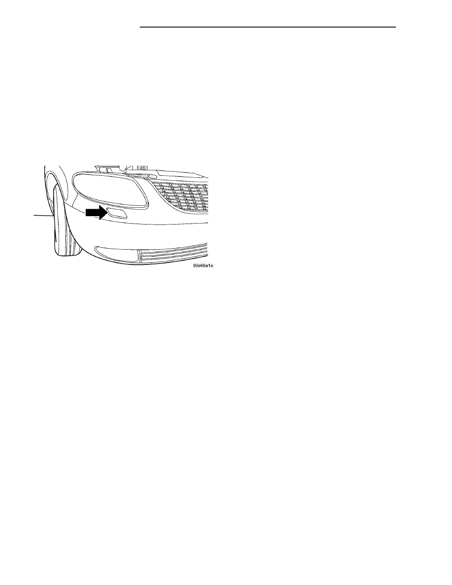
The headlamp washers on this vehicle (Fig. 3)

work in conjunction with the windshield washers.
The headlamp washers are enabled with the head-
lamps “ON” and the windshield washers activated.
With the windshield washers activated the headlamp
washers will spray twice for a predetermined amount
of time.

OPERATION

The headlamp washer system utilizes a separate

high pressure pump that is attached to the wind-
shield washer reservoir. The headlamp washer pump
feeds nozzles that are mounted in the front fascia of
the vehicle. The nozzle bodies have a telescopic
action that will extend the nozzles in front of the
headlamp assembly. These nozzles spray the head-
lamps when the system is activated.

To activate the headlamp washers, turn ON the

headlamps and them press the windshield washer
control knob. This will operate the windshield wash-
ers and direct two timed high pressure sprays onto
the headlamp lens.

DIAGNOSIS AND TESTING - HEADLAMP
WASHERS - EXPORT

The headlamp washer pump pick-up is located

above the low washer fluid level sensor. First of all
check the fluid level in the reservoir.

(1) Check fuse #30 for continuity. If no continuity,

go to Step 3.

(2) If the headlamp washers do not pop up when a

headlamp wash is requested, disconnect the head-
lamp washer hose. To disconnect the headlamp
washer hose, push down on the latch at any connec-
tor with slight force and pull apart. When reattach-
ing, push till you hear a snap. With a regulated 20
psi of air pressure, apply it to the washer hose. The
headlamp washers should pop up out of the front fas-
cia. If not, check for leaks/connections in the hose.

WARNING: IF MORE THAN 20 PSI IS APPLIED TO
THE WASHER HOSE, WASHER FLUID MAY SPRAY
OUT OF THE HEADLAMP WASHER. WEAR SAFETY
GLASSES AND DO NOT HAVE AIMING DIRECTLY
TOWARD FACE.

(3) If the hose and washer spray assembly are OK,

check the washer pump for ground and 12v power
during a washer request. If defective, repair circuit
as necessary.

Fig. 3 HEADLAMP WASHER LOCATION

8R - 10

WIPERS/WASHERS

RS

HEADLAMP WASHER TEST

CONDITION

POSSIBLE CAUSE

CORRECTION

HEADLAMP WASHER
SYSTEM WILL NOT FLOW
WASHER FLUID.

1. NO WASHER FLUID IN
RESERVOIR.

1. FILL RESERVOIR.

2. JUNCTION BLOCK FUSE
#5 BLOWN.

2. SHORT CIRCUIT BETWEEN JUNCTION BLOCK
FUSE #5 AND WIPER SWITCH TERMINAL #1.
SHORT IN WIPER SWITCH. IF NOT OK, REPAIR
CIRCUIT OR REFER TO WIPER/WASHER
SWITCH DIAGNOSTIC PROCEDURES.

3. HEADLAMP WASHER
HOSE NOT FLOWING FLUID.

3. ASSURE WASHER HOSE IS NOT PINCHED,
LOOSE, BROKEN, OR DISCONNECTED. IF NOT
OK, PROPERLY ROUTE OR REPAIR WASHER
HOSE.

4. MOTOR CONNECTOR
LOOSE.

4. PROPERLY SEAT CONNECTOR TO MOTOR.

5. MOTOR CONNECTOR
TERMINALS BENT.

5. REPAIR TERMINALS AND PROPERLY SEAT
CONNECTOR TO MOTOR.

6. OPEN POWER CIRCUIT
TO SWITCH.

6. OPEN OR DEFECTIVE CIRCUIT BETWEEN
JUNCTION BLOCK FUSE #5 AND WASHER
SWITCH CONNECTOR TERMINAL #1. IF NOT OK,
REPAIR CIRCUIT.

7. OPEN OR DEFECTIVE
WIPER/WASHER SWITCH.

7. CONNECT AN OHMMETER ACROSS WIPER/
WASHER SWITCH TERMINAL #1 AND #2 AND
DEPRESS WASHER BUTTON AND CHECK FOR
CONTINUITY. IF NOT OK, REFER TO WIPER/
WASHER SWITCH DIAGNOSTIC PROCEDURES.

8. OPEN POWER CIRCUIT
TO MOTOR.

8. OPEN OR DEFECTIVE CIRCUIT BETWEEN
WIPER/WASHER SWITCH CONNECTOR
TERMINAL #2 AND MOTOR CONNECTOR
TERMINAL #1. IF NOT OK, REPAIR CIRCUIT.

9. OPEN OR DEFECTIVE
MOTOR GROUND CIRCUIT.

9. OPEN OR DEFECTIVE CIRCUIT BETWEEN
WASHER MOTOR CONNECTOR GROUND
TERMINAL #2 AND LEFT HEADLAMP GROUND
#5 OR ENGINE GROUND #1 OR 2.

10. OPEN CIRCUIT IN
HEADLAMP WASHER
MOTOR.

10. CHECK FOR AN OPEN CIRCUIT ON MOTOR
BETWEEN POWER TERMINAL #1 AND GROUND
TERMINAL #2. IF NOT OK, REPLACE WASHER
MOTOR.

11. SEIZED MOTOR
BEARINGS.

11. APPLY DIRECT BATTERY VOLTAGE TO
MOTOR TERMINALS. IF MOTOR DOES NOT
RUN, REPLACE MOTOR.

12. DEFECTIVE HEADLAMP
WASHER RELAY.

12. REPLACE THE HEADLAMP WASHER RELAY.

ONE HEADLAMP WASHER
NOZZLE WILL NOT FLOW
WASHER FLUID.

1. HEADLAMP WASHER
HOSE NOT FLOWING FLUID.

1. REPAIR OR REPLACE THE HEADLAMP
WASHER HOSE.

2. PLUGGED HEADLAMP
WASHER NOZZLE.

2. REPLACE HEADLAMP WASHER NOZZLE.

RS

WIPERS/WASHERS

8R - 11

HEADLAMP WASHERS - EXPORT (Continued)

REMOVAL

(1) Disconnect and isolate the battery negative

cable.

(2) Hoist vehicle or support on jack stands.
(3) Disconnect the hose from the nozzle inlet. To

disconnect the headlamp washer hose, push down on
the latch with slight force and pull apart.

(4) Apply a regulated 20 psi of compressed air to

the inlet, so as to fully extend the telescopic unit.

WARNING: IF MORE THAN 20 PSI IS APPLIED TO
THE WASHER INLET, WASHER FLUID MAY SPRAY
OUT OF THE HEADLAMP WASHER. WEAR SAFETY
GLASSES AND DO NOT HAVE AIMING DIRECTLY
TOWARD FACE.

(5) Unsnap cover from telescopic assembly.
(6) Disconnect air supply from washer inlet to fully

retract the telescopic unit.

(7) Remove two screws holding the nozzle assem-

bly to the front fascia.

(8) Remove the nozzle assembly from behind fas-

cia.

INSTALLATION

(1) Place the nozzle assembly in behind the fascia.
(2) Install the two screws holding the nozzle

assembly to the front fascia.

(3) Snap cover onto telescopic assembly.

WARNING: IF MORE THAN 20 PSI IS APPLIED TO
THE WASHER INLET, WASHER FLUID MAY SPRAY
OUT OF THE HEADLAMP WASHER. WEAR SAFETY
GLASSES AND DO NOT HAVE AIMING DIRECTLY
TOWARD FACE.

On the new washer unit, there is a white tab with

pull ring holding the telescopic unit up approxi-
mately an inch. This is to ease the installation pro-
cess. Once cover is snapped on, you may either pull
up on the unit to remove the tab, or apply regulated
compressed air.

(4) Apply a regulated 20 psi of compressed air the

inlet, so as to fully extend the telescopic unit.

(5) With unit extended, pull white tab out from the

bottom of the telescopic unit and discard.

(6) Remove the air supply from the washer unit.
(7) Connect the washer hose to the telescopic unit.

Press firmly until snap is heard.

(8) Remove vehicle from hoist or jack stands.
(9) Connect the battery negative cable.
(10) Verify vehicle and system operation.

HEADLAMP WASHER HOSE -
EXPORT

REMOVAL

The headlamp washer hose is a special high pres-

sure hose with specific fittings, and must be replaced
as a unit.

(1) Disconnect and isolate the battery negative

cable.

(2) Hoist vehicle or support on jack stands.
(3) Remove parts as necessary to replace high

pressure headlamp washer hose. When disconnecting
hose, press down firmly on latch at headlamp washer
pump motor and telescopic washer assembly and pull
apart.

INSTALLATION

The headlamp washer hose is a special high pres-

sure hose with specific fittings, and must be replaced
as a unit.

(1) Install

the

new

high

pressure

headlamp

washer hose assembly. Push fitting on until a snap is
heard.

(2) Install the parts that were removed to replace

high pressure headlamp washer hose.

(3) Remove vehicle from hoist or jack stands.
(4) Connect the battery negative cable.
(5) Verify vehicle and system operation.

HEADLAMP WASHER PUMP
MOTOR - EXPORT

REMOVAL

(1) Disconnect and isolate the battery negative

cable.

(2) Remove the engine fresh air housing inside the

engine compartment (Refer to 9 - ENGINE/AIR
INTAKE

SYSTEM/AIR

CLEANER

HOUSING

-

REMOVAL).

(3) Disconnect the washer hose at the in-line con-

nector forward of the cowl grille so that the in-line
connector remains with the washer hose from the
fresh air plenum.

(4) Disconnect the washer hose from the hose clip

located on the front fender side shield.

(5) Remove the filler tube screw.
(6) Hoist and support vehicle on hoist or jack

stands.

(7) Remove the right front wheel and tire assembly

(Refer to 22 - TIRES/WHEELS - REMOVAL).

(8) Disconnect the left right front wheelhouse

splash shield and move aside (Refer to 23 - BODY/
EXTERIOR/WHEELHOUSE

SPLASH

SHIELD

-

REMOVAL).

8R - 12

WIPERS/WASHERS

RS

HEADLAMP WASHERS - EXPORT (Continued)

(9) Drain washer fluid from the reservoir and into

a suitable clean container. This can be done by dis-
connecting the windshield washer hose from the
front (outboard) washer pump and allowing the
washer fluid to drain into a container through a tem-
porary jumper hose connected to the front washer
pump.

(10) Disconnect the rear washer pump hose from

washer pump.

(11) Disconnect

the

high

pressure

headlamp

washer pump hose by pressing down firmly on latch
and pulling hose off.

(12) Disconnect the electrical body harness connec-

tors to the washer pump motors and the fluid level
sensor. Slide the red lock on the connector to the
release position, then, depress the black tab and pull
the connector off the pump or sensor.

(13) Remove the two reservoir mounting screws.
(14) Disconnect the reservoir from the body mount

by raising the reservoir upward slightly and then
down so that the reservoir filler neck and front
washer hose pull through the opening in the front
fender side shield.

(15) Remove pump from reservoir by pulling pump

up and away from reservoir cavity and out of mount-
ing grommet. Do not damage reservoir/pump sealing
surface or puncture reservoir during removal.

(16) Remove pump grommet and discard.

INSTALLATION

(1) Use new grommet when installing a new pump

assembly.

(2) Assure pump upper retention tab is pressed

into reservoir slot and assure the pump is aligned to
and fully seated in the reservoir cavity.

(3) Push filler neck and front washer hose through

the opening in the front fender side shield. Connect
the reservoir to the body mount by lowering the res-
ervoir down.

(4) Install the two reservoir mounting screws.

Torque screws to 8.5 - 11.3 N·m (75 - 100 in. lbs.).

(5) Connect the electrical body harness connectors

to the washer pump motors and the fluid level sen-
sor. Slide the red lock on the connector to the closed
or locked position.

(6) Connect front and rear washer pump hoses and

assure that they are properly routed to prevent
pinching and possible inoperative washers.

(7) Connect the high pressure headlamp washer

hose by firmly pushing hose onto inlet until a snap is
heard.

(8) Connect the left right front wheelhouse splash

shield and move aside (Refer to 23 - BODY/EXTERI-
OR/WHEELHOUSE SPLASH SHIELD - INSTALLA-
TION).

(9) Install the right front wheel and tire assembly

(Refer to 22 - TIRES/WHEELS - INSTALLATION).

(10) lower vehicle from hoist or jack stands.
(11) Install the filler tube screw. Torque screw to

8.5 - 11.3 N·m (75 - 100 in. lbs.).

(12) Connect the washer hose to the hose clip

located on the front fender side shield.

(13) Connect the washer hose at the in-line con-

nector forward of the cowl grille.

(14) Install the engine fresh air housing inside the

engine compartment (Refer to 9 - ENGINE/AIR
INTAKE

SYSTEM/AIR

CLEANER

HOUSING

-

INSTALLATION).

(15) Connect the battery negative cable.
(16) Verify vehicle and system operation.

REAR WASHER PUMP MOTOR

REMOVAL

(1) Disconnect and isolate the battery negative

cable.

(2) Remove the engine fresh air housing inside the

engine compartment (Refer to 9 - ENGINE/AIR
INTAKE

SYSTEM/AIR

CLEANER

HOUSING

-

REMOVAL).

(3) Disconnect the washer hose at the in-line con-

nector forward of the cowl grille so that the in-line
connector remains with the washer hose from the
fresh air plenum.

(4) Disconnect the washer hose from the hose clip

located on the front fender side shield.

(5) Remove the filler tube screw.
(6) Hoist and support vehicle on hoist or jack

stands.

(7) Remove the right front wheel and tire assembly

(Refer to 22 - TIRES/WHEELS - REMOVAL).

(8) Disconnect the left right front wheelhouse

splash shield and move aside (Refer to 23 - BODY/
EXTERIOR/WHEELHOUSE

SPLASH

SHIELD

-

REMOVAL).

(9) Drain washer fluid from the reservoir and into

a suitable clean container. This can be done by dis-
connecting the windshield washer hose from the
front (outboard) washer pump and allowing the
washer fluid to drain into a container through a tem-
porary jumper hose connected to the front washer
pump.

(10) Disconnect the electrical body harness connec-

tors to the washer pump motors and the fluid level
sensor. Slide the red lock on the connector to the
release position, then, depress the black tab and pull
the connector off the pump or sensor.

(11) Remove the two reservoir mounting screws.

RS

WIPERS/WASHERS

8R - 13

HEADLAMP WASHER PUMP MOTOR - EXPORT (Continued)


Content   ..  139  140  141  142   ..