Chrysler Town, Dodge Caravan. Manual - part 31


  Index      Chrysler     Chrysler TOWN & COUNTRY, VOYAGER, Dodge Caravan - service repair manual 2001-2007 year


Search            


Content   ..  29  30  31  32   ..


Chrysler Town, Dodge Caravan. Manual - part 31


INSTALLATION

CAUTION: Propeller shaft installation is a two-man
operation. Never allow propeller shaft to hang while
connected to power transfer unit (PTU) or rear driv-
eline module flanges. A helper is required.

(1) Make sure transaxle is in Neutral (N) position.
(2) Obtain a helper and lift propeller shaft assem-

bly into position (Fig. 1).

(3) While helper supports front half of shaft level

to underbody, align paint marks at driveline module
flange and install three propeller shaft rubber cou-

pler-to-rear driveline module bolts by hand. Do not
torque at this time.

(4) While helper supports front half of shaft level

to underbody, align chalk marks at PTU flange.
Install six propeller shaft-to-PTU flange bolts and
torque to 30 N·m (22 ft. lbs.). Torque bolts alternately
to ensure proper flange mating.

(5) Place center bearing into position. Install and

torque center bearing-to-crossmember bolts to 54
N·m (40 ft. lbs.).

(6) Torque propeller shaft rubber coupler-to-rear

driveline module assembly to 54 N·m (40 ft. lbs.).

SPECIFICATIONS - PROPELLER SHAFT

TORQUE SPECIFICATIONS

DESCRIPTION

N·m

Ft. Lbs.

In. Lbs.

Bolt, Propeller Shaft Front Flange-to-PTU Flange

30

22

Bolt, Propeller Shaft Rear Flange-to-Driveline

Module Flange

54

40

Bolt, Center Support Bearing-to-Body

54

40

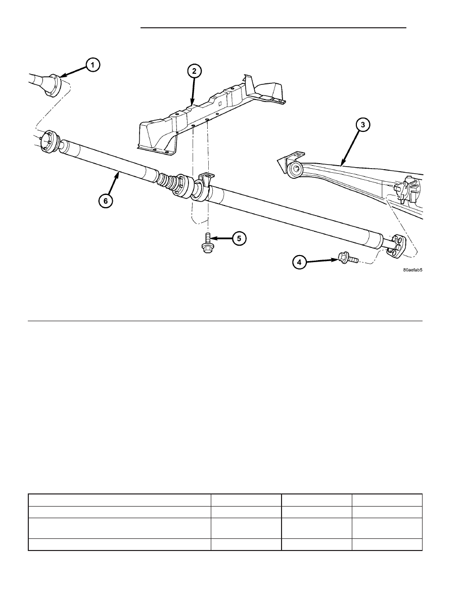
Fig. 1 Propeller Shaft Removal/Installation

1 - PTU FLANGE

3 - REAR DRIVELINE MODULE

5 - BOLT-CENTER SUPPORT BEARING-TO-
CROSSMEMBER

2 - CROSSMEMBER

4 - BOLT-PROPELLER SHAFT COUPLER-
T0-DRIVELINE MODULE

6 - PROPELLER SHAFT ASSEMBLY

3 - 22

PROPELLER SHAFT

RS

PROPELLER SHAFT (Continued)

REAR DRIVELINE MODULE

TABLE OF CONTENTS

page

page

REAR DRIVELINE MODULE

DESCRIPTION

. . . . . . . . . . . . . . . . . . . . . . . . . 23

OPERATION

. . . . . . . . . . . . . . . . . . . . . . . . . . . 23

DIAGNOSIS AND TESTING

DIAGNOSIS AND TESTING - REAR

DRIVELINE MODULE NOISE . . . . . . . . . . . . . 24

DIAGNOSIS AND TESTING - REAR

DRIVELINE MODULE OPERATION . . . . . . . . 26

REMOVAL

. . . . . . . . . . . . . . . . . . . . . . . . . . . . . 26

DISASSEMBLY

. . . . . . . . . . . . . . . . . . . . . . . . . 27

ASSEMBLY

. . . . . . . . . . . . . . . . . . . . . . . . . . . . 29

INSTALLATION

. . . . . . . . . . . . . . . . . . . . . . . . . 33

SPECIFICATIONS - REAR DRIVELINE

MODULE

. . . . . . . . . . . . . . . . . . . . . . . . . . . . 34

SPECIAL TOOLS

. . . . . . . . . . . . . . . . . . . . . . . 34

BI-DIRECTIONAL OVERRUNNING CLUTCH

DESCRIPTION

. . . . . . . . . . . . . . . . . . . . . . . . . 34

OPERATION

. . . . . . . . . . . . . . . . . . . . . . . . . . . 36

DIFFERENTIAL ASSEMBLY

DESCRIPTION

. . . . . . . . . . . . . . . . . . . . . . . . . 39

OPERATION

. . . . . . . . . . . . . . . . . . . . . . . . . . . 39

FLUID - DIFFERENTIAL ASSEMBLY

STANDARD PROCEDURE - DIFFERENTIAL

ASSEMBLY FLUID CHANGE

. . . . . . . . . . . . . 40

FLUID - OVERRUNNING CLUTCH HOUSING

STANDARD PROCEDURE - OVERRUNNING

CLUTCH HOUSING FLUID CHANGE

. . . . . . . 41

VISCOUS COUPLER

DESCRIPTION

. . . . . . . . . . . . . . . . . . . . . . . . . 41

OPERATION

. . . . . . . . . . . . . . . . . . . . . . . . . . . 42

TORQUE ARM

REMOVAL

. . . . . . . . . . . . . . . . . . . . . . . . . . . . . 44

INSTALLATION

. . . . . . . . . . . . . . . . . . . . . . . . . 44

INPUT FLANGE SEAL

REMOVAL

. . . . . . . . . . . . . . . . . . . . . . . . . . . . . 44

INSTALLATION

. . . . . . . . . . . . . . . . . . . . . . . . . 45

OUTPUT FLANGE SEAL

REMOVAL

. . . . . . . . . . . . . . . . . . . . . . . . . . . . . 45

INSTALLATION

. . . . . . . . . . . . . . . . . . . . . . . . . 46

REAR DRIVELINE MODULE

DESCRIPTION

The rear driveline module assembly (Fig. 1) con-

sists of four main components:

• Bi-Directional Overrunning Clutch (BOC)

• Viscous Coupling

• Differential Assembly

• Torque Arm
The viscous coupling and bi-directional overrun-

ning clutch are contained within an overrunning
clutch housing, which fastens to the differential
assembly. The overrunning clutch housing and differ-
ential assembly have unique fluid sumps, each
requiring their own type and capacity of fluid. The
overrunning clutch housing requires Mopar

t ATF+4

(Automatic Transmission Fluid—Type 9602) or equiv-
alent. The differential assembly requires Mopar

t

80W-90 Gear and Axle Lubricant.

Driveline module service is limited to the following

components:

• Differential Assembly (serviced only as assem-

bly)

• Viscous Coupling

• Bi-Directional Overrunning Clutch (BOC)

• Overrunning Clutch Housing

• Seals (Input Flange, Output Flange, Overrun-

ning Clutch Housing O-rings)

• Input Flange/Shield

• Torque Arm

• Vents

• Fasteners

OPERATION

The primary benefits of All Wheel Drive are:
• Superior straight line acceleration, and corner-

ing on all surfaces

• Better traction and handling under adverse con-

ditions, resulting in improved hill climbing ability
and safer driving.

The heart of the system is an inter-axle viscous

coupling. The vehicle retains predominantly front-
wheel drive characteristics, but the All Wheel Drive
capability takes effect when the front wheels start to
slip. Under normal level road, straight line driving,
100% of the torque is allocated to the front wheels.
The viscous coupling controls and distributes torque/
power to the rear wheels. The viscous coupling trans-
mits torque to the rear wheels in proportion of the
amount of the slippage at the front wheels. Thais
variable torque distribution is automatic with no
driver inputs required. The coupling is similar to a
multi-plate clutch. It consists of a series of closely
spaced discs, which are alternately connected to the

RS

REAR DRIVELINE MODULE

3 - 23

front and rear drive units. The unit is totally sealed
and partially filled with silicone fluid. There is no
adjustment, maintenance or fluid checks required
during the life of the unit.

The overrunning clutch allows the rear wheels to

overrun the front wheels during a rapid front wheel
lock braking maneuver. The overrunning action pre-
vents any feed-back of front wheel braking torque to
the rear wheels. It also allows the braking system to
control the braking behavior as a two wheel drive
(2WD) vehicle.

The overrunning clutch housing has a separate oil

sump and is filled independently from the differen-
tial. The fill plug is located on the side of the over-
running clutch case. When filling the overrunning
clutch with lubricant use Mopar

t ATF+4 (Automatic

Transmission Fluid—Type 9602) or equivalent.

The differential assembly contains a conventional

open differential with hypoid ring gear and pinion
gear set. The hypoid gears are lubricated by SAE
80W-90 gear lubricant.

DIAGNOSIS AND TESTING

DIAGNOSIS AND TESTING - REAR DRIVELINE
MODULE NOISE

Different sources can be the cause of noise that the

rear driveline module assembly is suspected of mak-
ing. Refer to the following causes for noise diagnosis.

DRIVELINE MODULE ASSEMBLY NOISE

The most important part of driveline module ser-

vice is properly identifying the cause of failures and
noise complaints. The cause of most driveline module
failures is relatively easy to identify. The cause of
driveline module noise is more difficult to identify.

If vehicle noise becomes intolerable, an effort

should be made to isolate the noise. Many noises that
are reported as coming from the driveline module
may actually originate at other sources. For example:

• Tires

• Road surfaces

• Wheel bearings

Fig. 1 AWD Driveline Module Assembly

1 - TORQUE ARM

8 - WASHER

15 - PLUG-OVERRUNNING CLUTCH
HOUSING DRAIN

2 - INPUT FLANGE

9 - BI-DIRECTIONAL OVERRUNNING
CLUTCH (BOC)

16 - SNAP RING

3 - FLANGE NUT

10 - VISCOUS COUPLER

17 - BEARING

4 - WASHER

11 - SHIM (SELECT)

18 - OVERRUNING CLUTCH HOUSING

5 - SHIELD

12 - O-RING

19 - SEAL-INPUT FLANGE

6 - VENT

13 - DIFFERENTIAL ASSEMBLY

7 - O-RING

14 - PLUG-DIFFERENTIAL FILL

3 - 24

REAR DRIVELINE MODULE

RS

REAR DRIVELINE MODULE (Continued)

• Engine

• Transmission

• Exhaust

• Propeller shaft (vibration)

• Vehicle body (drumming)
Driveline module noises are normally divided into

two categories: gear noise or bearing noise. A thor-
ough and careful inspection should be completed to
determine the actual source of the noise before
replacing the driveline module.

The rubber mounting bushings help to dampen-out

driveline module noise when properly installed.
Inspect to confirm that no metal contact exists
between the driveline module case and the body. The
complete isolation of noise to one area requires
expertise and experience. Identifying certain types of
vehicle noise baffles even the most capable techni-
cians. Often such practices as:

• Increase tire inflation pressure to eliminate tire

noise.

• Listen for noise at varying speeds with different

driveline load conditions

• Swerving the vehicle from left to right to detect

wheel bearing noise.

All driveline module assemblies produce noise to a

certain extent. Slight carrier noise that is noticeable
only at certain speeds or isolated situations should be
considered normal. Carrier noise tends to peak at a
variety of vehicle speeds. Noise is NOT ALWAYS an
indication of a problem within the carrier.

TIRE NOISE

Tire noise is often mistaken for driveline module

noise. Tires that are unbalanced, worn unevenly or
are worn in a saw-tooth manner are usually noisy.
They often produce a noise that appears to originate
in the driveline module.

Tire noise changes with different road surfaces, but

driveline module noise does not. Inflate all four tires
with approximately 20 psi (138 kPa) more than the
recommended inflation pressure (for test purposes
only). This will alter noise caused by tires, but will
not affect noise caused by the differential. Rear axle
noise usually ceases when coasting at speeds less
than 30 mph (48 km/h); however, tire noise contin-
ues, but at a lower frequency, as the speed is
reduced.

After test has been completed lower tire pressure

back to recommended pressure.

GEAR NOISE (DRIVE PINION AND RING GEAR)

Abnormal gear noise is rare and is usually caused

by scoring on the ring gear and drive pinion. Scoring
is the result of insufficient or incorrect lubricant in
the carrier housing.

Abnormal gear noise can be easily recognized. It

produces a cycling tone that will be very pronounced
within a given speed range. The noise can occur dur-
ing one or more of the following drive conditions:

• Drive

• Road load

• Float

• Coast
Abnormal gear noise usually tends to peak within

a narrow vehicle speed range or ranges. It is usually
more pronounced between 30 to 40 mph (48 to 64
km/h) and 50 to 60 mph (80 to 96 km/h). When objec-
tionable gear noise occurs, note the driving condi-
tions and the speed range.

BEARING NOISE (DRIVE PINION AND
DIFFERENTIAL)

Defective bearings produce a rough growl that is

constant in pitch and varies with the speed of vehi-
cle. Being aware of this will enable a technician to
separate bearing noise from gear noise.

Drive pinion bearing noise that results from defec-

tive or damaged bearings can usually be identified by
its constant, rough sound. Drive pinion front bearing
is usually more pronounced during a coast condition.
Drive pinion rear bearing noise is more pronounced
during a drive condition. The drive pinion bearings
are rotating at a higher rate of speed than either the
differential side bearings or the axle shaft bearing.

Differential side bearing noise will usually produce

a constant, rough sound. The sound is much lower in
frequency than the noise caused by drive pinion bear-
ings.

Bearing noise can best be detected by road testing

the vehicle on a smooth road (black top). However, it
is easy to mistake tire noise for bearing noise. If a
doubt exists, the tire treads should be examined for
irregularities that often causes a noise that resem-
bles bearing noise.

ENGINE AND TRANSMISSION NOISE

Sometimes noise that appears to be in the driv-

eline module assembly is actually caused by the
engine or the transmission. To identify the true
source of the noise, note the approximate vehicle
speed and/or RPM when the noise is most noticeable.
Stop the vehicle next to a flat brick or cement wall
(this will help reflect the sound). Place the transaxle
in NEUTRAL. Accelerate the engine slowly up
through the engine speed that matches the vehicle
speed noted when the noise occurred. If the same
noise is produced, it usually indicates that the noise
is being caused by the engine or transaxle.

RS

REAR DRIVELINE MODULE

3 - 25

REAR DRIVELINE MODULE (Continued)


Content   ..  29  30  31  32   ..