Chrysler Crossfire. Manual - part 829


  Index      Chrysler     Chrysler Crossfire - service repair manual 2005 year


Search            


Content   ..  827  828  829  830   ..


Chrysler Crossfire. Manual - part 829


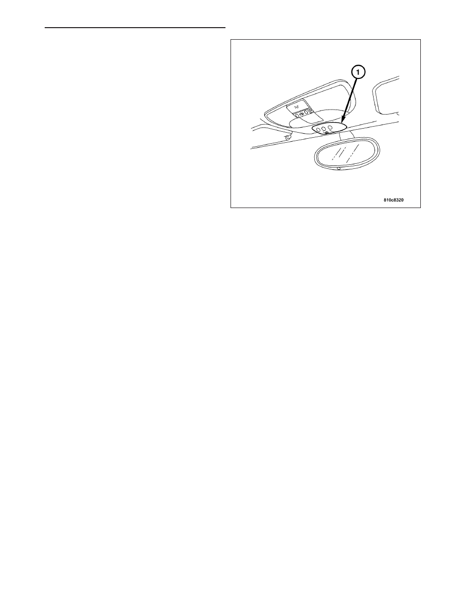
The TPM module (1) performs diagnostic routines,
stores Diagnostic Trouble Codes (DTCs) and provides
the appropriate lamp status to the Body Control Mod-
ule (BCM). When the module determines there is a
fault, the low tire pressure indicator lamp circuit is
grounded and the BCM turns on the “Low Tire” pres-
sure indicator lamp.

The TPM module (1) also stores its own identification
number, each of the four sensor/transmitter identifica-
tion

numbers,

module

version

and

the

date

of

manufacture.

STANDARD PROCEDURE - TPM MODULE PROGRAMMING

If a TPM module fails, or one or more tire pressure sensor/transmitters fail, the TPM module’s diagnostic memory
must be cleared and reprogrammed after replacement. This is necessary for the module to detect which wheel is
sending the signal.

Refer to the following procedure to program the module for identification of tire pressure sensor/transmitters.

Note: The vehicle’s tires must not have been rotated above 8 km/h (5 MPH) in the last two minutes prior to
programming.

1. Connect a DRB III

T

scan tool to the vehicle’s diagnostic connector beneath the instrument panel near the steer-

ing column.

2. Access the Chassis System using the DRB III

T

.

3. Once in the Chassis System; select Tire Pressure Monitor, then select Miscellaneous Functions.

4. Select Train All Mode from the System Test screen displaying the following options:

Tire Set

Train All Mode

Stop Train Mode

5. Place the magnet, Special Tool 8821, at the valve stem for that wheel as directed by the DRB III

T

.

6. When each wheel’s pressure sensor/transmitter has been programmed, the DRB III

T

will automatically direct you

to the next wheel sensor/transmitter to be programmed.

Note: When programming the module (all four sensor/transmitters), the magnet should be moved from
wheel to wheel in a clockwise direction starting at the left front wheel.

7. Remove the magnet and move to each of the remaining wheels as directed by the DRB III

T

. Each sensor/trans-

mitter will automatically sense the presence of the magnet and begin programming.

8. Once “Training Completed” is displayed, exit the program function screen.

9. Verify that the module programming is complete by looking at the tire pressure sensor/tire pressure readings in

the Sensor Display using the DRB III

T

.

10. Once programming is complete, select Stop Train Mode from the System Test screen.

ZH

TIRES/WHEELS - SERVICE INFORMATION

22 - 49

REMOVAL

1. Using a plastic wedge. Slide the wedge under the

Universal Garage Door Opener/Tire Pressure Mon-
itor module (1) and the headliner and pry the TPM
(1) away from the headliner.

INSTALLATION

1. Install the Universal Garage Door Opener/Tire

Pressure Monitor (1) by snapping it into the
headliner.

SENSOR

DESCRIPTION

CAUTION: The use of tire sealants is strictly prohibited for vehicles equipped with the Tire Pressure Mon-
itoring system. Tire sealants can clog tire pressure sensors.

CAUTION: Tire pressure sensor valve stem caps and cores are specially designed for the sensors. Due to
risk of corrosion, do not use a standard valve stem cap or core in a tire pressure sensor in place of the
original equipment style sensor cap and core.

22 - 50

TIRES/WHEELS - SERVICE INFORMATION

ZH

CAUTION: Do not attempt to install a tire pressure sensor in a steel wheel or aftermarket wheel. Use tire
pressure sensors in original style factory wheels only.

A tire pressure sensor/transmitter is installed in each wheel of this vehicle as part of the tire pressure monitoring
system. A special valve stem incorporated into each tire pressure sensor/transmitter attaches it to the wheel.

VALVE STEM CORE AND CAP

On this vehicle, the valve stem is part of the tire pressure sensor/transmitter and is used as its antenna. If corrosion
were to develop in the valve stem, it would affect the ability of the tire pressure sensor/transmitter to send the radio
frequency signal to the TPM module.

The valve stem used on this vehicle is made from aluminum. Corrosion of aluminum will be caused by putting a
dissimilar metal in contact with it. To prevent this type of corrosion from developing within the valve stem, the core
of the valve stem is made of a compatible metal and is specially coated.

For this reason, a standard valve stem core must never be installed in this valve stem. If the core of the valve stem
is removed when servicing the tire, the original valve stem core must be reinstalled. If the valve stem core needs to
be replaced, it must be replaced with an original equipment valve stem core.

The valve stem caps used on this vehicle are specially designed for their use on the valve stem of the tire pressure
sensor/transmitter. Each valve stem cap has an O-ring in the upper end of the valve stem cap to provide a positive
seal at the end of the valve stem. This keeps dirt, contamination and corrosion out of the valve stem caused by
moisture. As listed earlier, these conditions can affect the ability of the tire pressure transmitter to send the radio
frequency signal to the TPM module.

OPERATION

Each Tire Pressure Sensor/Transmitter serves three functions:

It is used as a valve stem to inflate and deflate the tire.

It periodically measures tire pressure. (Approximately every 30 seconds.)

It transmits the tire pressure value to the Tire Pressure Monitor (TPM) module in the vehicle. (Approximately
every 60 seconds or if tire pressure changes by one psi or more between transmissions.)

The system operates by monitoring a radio frequency transmission from the sensor/transmitters located in each
wheel. When the vehicle reaches a speed of approximately 32 km/h (20 MPH), centrifugal force created by the
rotating wheels closes a roll switch inside each sensor/transmitter, powering up the circuitry.

The sensor/transmitters will only send out information when vehicle speed is above 32 km/h (20 MPH). To facilitate
transmitting the radio signal to the TPM module, the valve stem acts as the antenna for the tire pressure sensor/
transmitter. When the TPM module senses that pressure is below one of two calibrated thresholds, (low pressure or
critical pressure) the TPM system will set a diagnostic trouble code and indirectly operate the “Low Tire” pressure
indicator lamp and the chime tone through the Body Control Module (BCM).

The tire pressure sensor/transmitter is powered by an internal battery. The battery is not replaceable separately. In
the event of battery failure, the entire tire pressure sensor/transmitter at that wheel will require replacement. To
extend the life of the battery, the sensor/transmitter is not activated until the vehicle reaches a speed of approxi-
mately 32 km/h (20 MPH) as stated earlier.

Each tire pressure sensor/transmitter has a unique identity code. This will allow the TPM system to indicate to a
technician, through Diagnostic Trouble Codes (DTCs) in the module, which tire of the vehicle has lost air pressure.
This code is also used to identify to a technician which pressure sensor/transmitter has set a DTC. For this reason,
if a tire pressure sensor/transmitter needs to be replaced, the new sensor/transmitter must be programmed to have
its identity code recognized by the receiver.

REMOVAL

CAUTION: When removing the stick-on balancing weights from the wheel, do not use an abrasive cleaner or
a cleaner which will damage the protective finish on the wheel.

Note: The cap used on this valve stem contains an O-ring seal to prevent contamination and moisture from
entering the valve stem. Retain this valve stem cap for reuse. Do not substitute a regular valve stem cap in
its place.

ZH

TIRES/WHEELS - SERVICE INFORMATION

22 - 51

Note: The valve stem used on this vehicle is made of aluminum and the core is nickel plated brass. The
original valve stem core must be reinstalled and not substituted for a valve stem core made of a different
material. This is required to prevent corrosion in the valve stem caused by the different metals.

1. Remove the tire/wheel from the vehicle.

2. Remove the balancing weights from the wheel (1).

3. Remove the cap from the valve stem (2).

4. Using the appropriate tool, remove the core (4)

from the valve stem (2).

5. Allow the tire fully deflate.

CAUTION:

The

pressure

transmitter

must

be

removed from the wheel and dropped into the tire
prior to breaking the bead and dismounting the
tire. Failure to do this will greatly increase the risk
of damaging the transmitter when servicing the
tire.

6. Remove the nut (1) mounting the valve stem (4) of

the pressure sensor/transmitter to the wheel (2).
Drop sensor/transmitter into the tire (3).

CAUTION: When breaking the top and bottom
bead of the tire off the wheel, care must be used
so the bead breaking mechanism on the tire
changer does not damage the wheel. This includes
the surface of the wheel flange on the inside of
the wheel.

7. Using the tire changer manufacturer’s procedure,

first break down the upper bead of the tire. Then
break down the bottom bead of the tire.

CAUTION: When dismounting the upper tire bead from the wheel, the proper procedure must be used. Not
using the proper procedure will result in damage to the wheel and tire.

22 - 52

TIRES/WHEELS - SERVICE INFORMATION

ZH


Content   ..  827  828  829  830   ..