Chrysler Crossfire. Manual - part 788


  Index      Chrysler     Chrysler Crossfire - service repair manual 2005 year


Search            


Content   ..  786  787  788  789   ..


Chrysler Crossfire. Manual - part 788


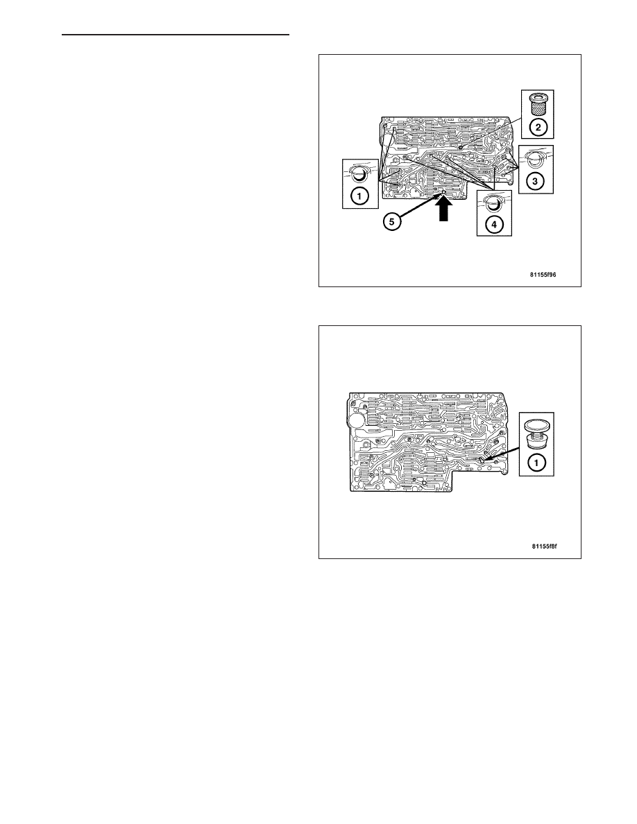
Note: A total of 12 valve balls are located in the
valve body, four made from plastic (4) and eight
from steel (1, 3).

5. Install all of the check balls (1, 3, 4) and the central

strainer (2).

6. Install the strainer in the inlet to the torque con-

verter lock-up control solenoid valve (1).

ZH

AUTOMATIC - NAG1 SERVICE INFORMATION

21 - 301

7. Position the sealing plate (3) onto the valve body

(4).

8. Install the valve housing (2) onto the valve body (4)

and sealing plate (3).

9. Install the shift plate bolts (1). Tighten the bolts to 8

N·m (71 in. lbs.).

10. Install the leaf spring (5).

11. Install the strainers (1) for the modulating pressure

and shift pressure control solenoid valves into the
valve housing.

21 - 302

AUTOMATIC - NAG1 SERVICE INFORMATION

ZH

12. Install the electrohydraulic control module (12)

onto the shift plate (13).

13. Bend the retaining lug on the stiffening rib on the

transmission oil temperature sensor to retain the
electrohydraulic control module.

14. Install the solenoid valves (6 - 11) into the shift

plate (13).

Note: Check the O-rings on the solenoid valves for
damage and replace if necessary.

15. Install the leaf springs (5).

16. Install the bolts (3, 4). Tighten the bolts to 8 N·m

(71 in. lbs.).

Note: Pay attention to the different lengths of the
bolts.

17. Install the solenoid caps (1, 2).

18. Install the electrohydraulic unit into the vehicle. (Refer to 21 - TRANSMISSION/TRANSAXLE/AUTOMATIC -

NAG1/ELECTROHYDRAULIC UNIT - INSTALLATION).

INSTALLATION

1. Position the electrohydraulic unit in the transmis-

sion housing.

2. Insert the selector valve (1) in the driver of the

detent plate (2). When installing the electrohydrau-
lic control module in the transmission housing, the
plastic part of the selector valve (1) must engage in
the driver of the detent plate (2).

ZH

AUTOMATIC - NAG1 SERVICE INFORMATION

21 - 303

3. Install the bolts (3) and tighten to 8 N·m (71 in.

lbs.).

4. Install a new oil filter..

5. Install the oil pan (5) and torque the oil pan bolts to

8 N·m (71 in. lbs.).

6. Install the oil drain plug (8) with a new drain plug

gasket (9). Torque the drain plug to 20 N·m (177 in.
lbs.).

7. Install the guide bushing (12) into the transmission

housing and install the bolt (11) to hold the guide
bushing in place.

8. Check the O-ring on the plug connector (1), and

replace if necessary.

9. Install the plug connector (1) into the guide bushing

(2). Turn the bayonet lock of the guide bushing (2)
clockwise to connect plug connector (1).

21 - 304

AUTOMATIC - NAG1 SERVICE INFORMATION

ZH


Content   ..  786  787  788  789   ..